
NEO-Edge40 Hardware
This page identifies the hardware blocks on the NEO-Edge40 Rev. 1.0 mainboard. If you are new to the product, start with the NEO-Edge40 Overview.
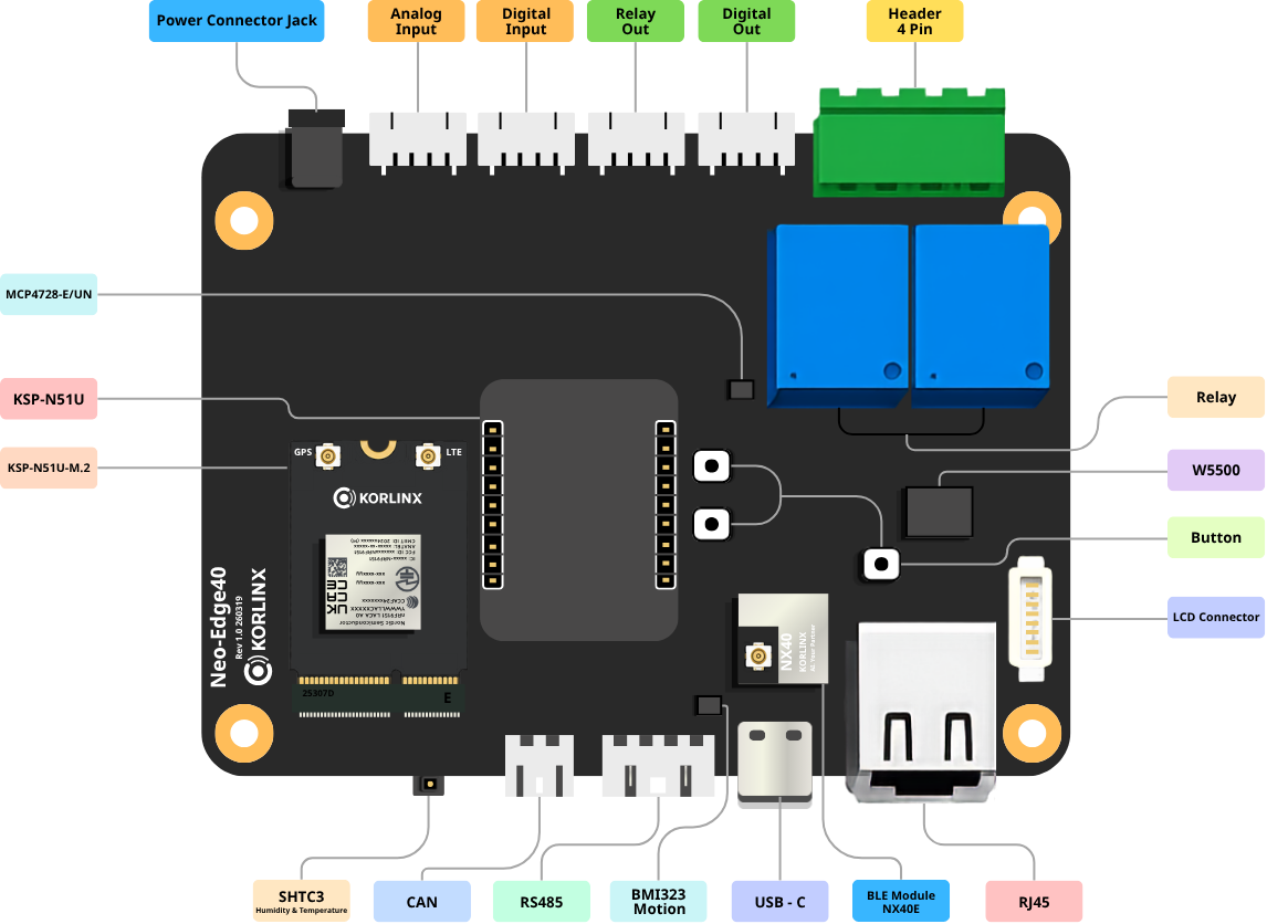
Development status: The board-level information below describes Rev. 1.0. The LCD, enclosure, output ratings, analog accuracy, isolation ratings, connector pinouts, and certification-related values are not final production specifications unless explicitly confirmed.
Hardware map
| Area | Hardware | Purpose |
|---|---|---|
| Main control | KORLINX NX40 module | BLE / Zigbee communication, edge processing, and control logic |
| Cellular expansion | KSP-N51U or KSP-N51U-M.2 | Optional LTE-M / NB-IoT communication |
| Wired communication | RJ45, RS-485, and CAN | Connects LAN systems, industrial devices, and controllers |
| Field inputs | Analog and digital input connectors | Receives sensor and contact signals |
| Field outputs | Relay, DC, and analog output connectors | Controls connected field equipment |
| Development | USB-C, SWD, GPIO, and I²C | Firmware, debugging, and peripheral expansion |
| Onboard sensors | BMI323 and SHTC3 | Motion and temperature/humidity sensing |
| Local interface | Button and LCD connector | Local input and planned status display |
| Power | DC power jack | Main board power input |
Main controller and wireless
| Item | Specification |
|---|---|
| Module | KORLINX NX40 |
| MCU | Nordic Semiconductor nRF52840, Arm Cortex-M4F at 64 MHz |
| Memory | 1 MB flash and 256 KB RAM |
| Wireless role | BLE and Zigbee data acquisition and control |
| Development environment | Arduino IDE with the NX40 board package and libraries |
The NX40 module handles wireless communications, field-data processing, protocol conversion, and I/O control.
Communication interfaces
| Interface | Board implementation | Typical use |
|---|---|---|
| Ethernet | 10/100 Ethernet through an RJ45 port and W5500 controller | LAN, PC, local server, or gateway uplink |
| RS-485 | One isolated channel | Industrial equipment and protocols such as Modbus RTU |
| CAN | One channel | CAN-based equipment or controllers |
| Cellular | Expansion for KSP-N51U or KSP-N51U-M.2 | LTE-M / NB-IoT connectivity at remote sites |
Industrial I/O
| I/O | Channels | Electrical function |
|---|---|---|
| Analog input | 2 | Selectable 4–20 mA or 0–5 V input |
| Analog output | 2 | 4–20 mA current output circuit |
| Digital input | 2 | 12 V opto-isolated input |
| Relay output | 2 | Contact output for switching external AC or DC loads |
| DC output | 2 | 12 V transistor low-side output |
| GPIO | Project-dependent | Additional control or status signals |
Potential loads include warning lights, pumps, fans, solenoid valves, auxiliary contactors, and industrial actuators. Verify electrical ratings and protection requirements before connecting a load.
Development and expansion
| Interface | Purpose |
|---|---|
| USB-C | Board connection, serial communication, or firmware work, depending on firmware configuration |
| SWD | Firmware download and debugging |
| GPIO | External signal access and control |
| I²C | Sensor or peripheral expansion |
| 4-pin header | Project-specific expansion |
Front LCD and Local UI
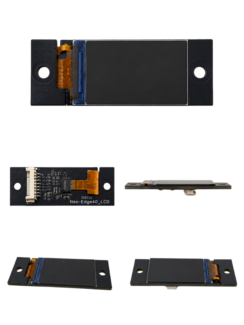
NEO-Edge40 is planned to use a 1.06-inch front LCD for field installation and status checking.
The LCD can be used to display operating status, communication status, sensor values, output status, alarm diagnostics, and basic settings.
| Screen Item | Displayed Content |
|---|---|
| Operating Status | Booting, Normal, Warning, Fault, Maintenance Mode |
| Communication Status | BLE device count, Zigbee node/network status, Ethernet link, RS-485/CAN, LTE registration and signal status |
| Measured Values | 4–20 mA / 0–5 V converted values, temperature/humidity, internal sensor values |
| Output Status | Relay 1/2, DC Output 1/2, analog output, GPIO status |
| Alarm / Diagnostics | Sensor disconnection, out-of-range value, communication failure, power or equipment error codes |
| Settings | Device ID, communication parameters, thresholds, and basic network information |
The LCD helps reduce the need to connect a laptop during installation or inspection.