
NX15 Quick Start
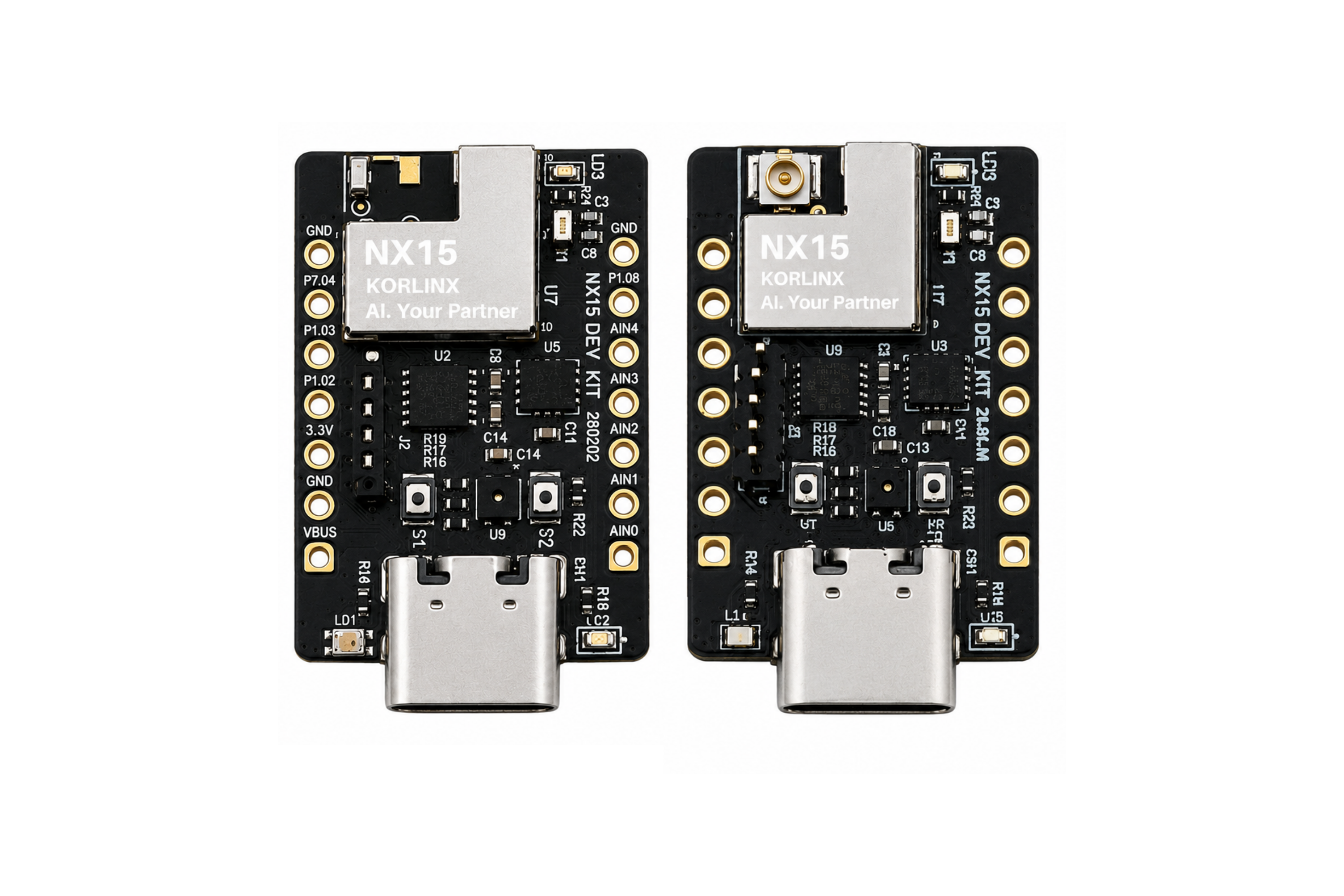
This guide helps you bring up the NX15 Series BLE module for the first time.
Use this page when you want to:
- Evaluate the NX15 module with DEV-NX15
- Prepare a custom PCB for NX15 bring-up
- Confirm power, debug, firmware, and basic BLE operation
- Start development with nRF Connect SDK / Zephyr RTOS
This page focuses on the first bring-up flow. Detailed PCB layout, antenna design, and low-power optimization are covered in separate pages to avoid duplicated content.
Quick Start Flow
| Step | Action | Expected Result |
|---|---|---|
| 1 | Select the NX15 variant | Antenna and Flash option match the project requirement |
| 2 | Prepare the hardware | DEV-NX15 or custom PCB is ready |
| 3 | Check power | 1.7–3.6 V supply path is correct |
| 4 | Prepare programming/debugging | SWDIO, SWDCLK, GND, and reset access are available |
| 5 | Prepare firmware environment | nRF Connect SDK / Zephyr RTOS workflow is ready |
| 6 | Flash a basic firmware example | Firmware starts running on the board |
| 7 | Verify basic operation | LED, UART log, BLE advertising, or debug output is confirmed |
| 8 | Continue application development | BLE, sensors, GPIO, and low-power features can be added |
1. Select the NX15 Variant
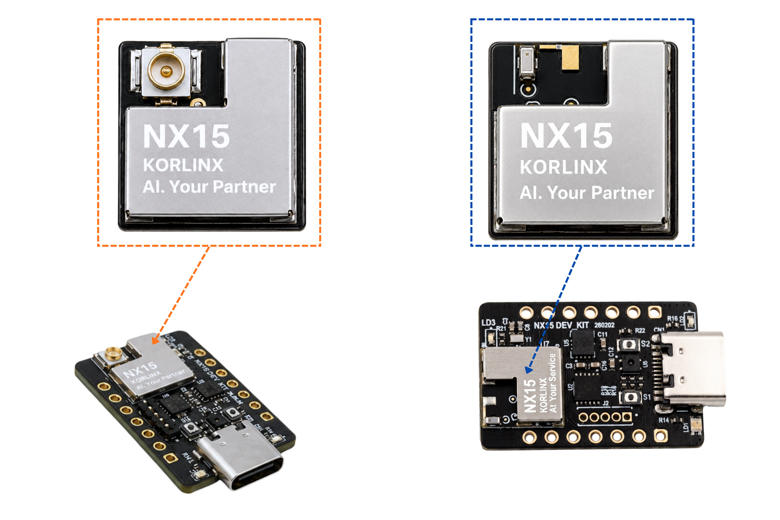
Choose the NX15 variant based on antenna type and Flash requirement.
| Model | Antenna | Flash | Use When |
|---|---|---|---|
| NX15i32 | Chip antenna | 32 Mbit SPI Flash | You need compact antenna integration and external Flash |
| NX15E32 | u.FL connector | 32 Mbit SPI Flash | You need an external antenna and external Flash |
| NX15i00 | Chip antenna | None | You need compact module integration without external Flash |
| NX15E00 | u.FL connector | None | You need an external antenna without external Flash |
For first evaluation, use the same antenna type that your final product is expected to use. Antenna choice can affect RF performance, layout requirements, and enclosure design.
2. Prepare the Hardware
There are two common bring-up paths.
Option A — DEV-NX15 Development Kit
Use DEV-NX15 when you want to evaluate the NX15 module quickly before designing custom hardware.
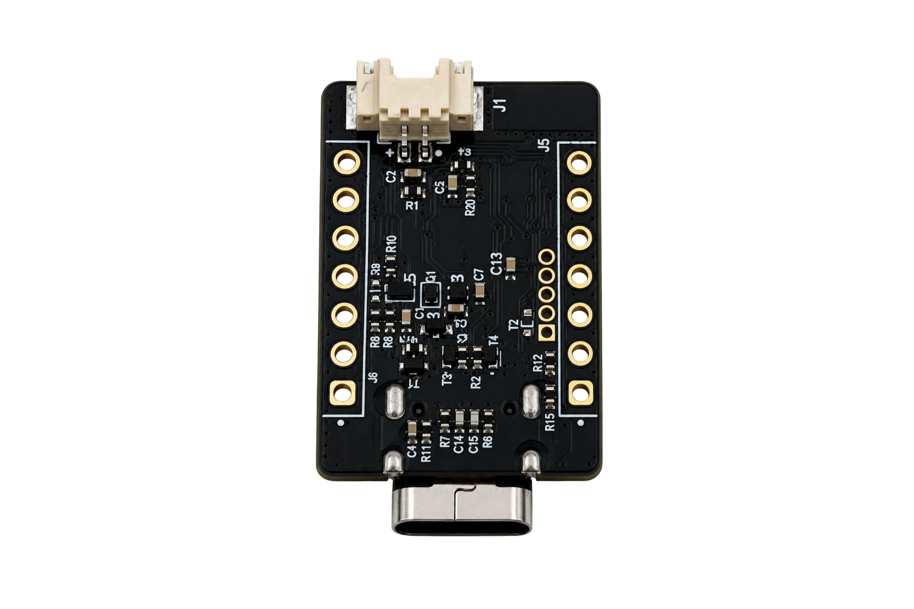
| Block | What to Check |
|---|---|
| USB Type-C | Connect the board to the PC |
| Debug access | Prepare SWD connection if required |
| LEDs / buttons | Use them for basic firmware tests |
| Sensors | Use them later for application examples |
| Battery connector | Use only when battery-powered testing is required |
Basic preparation:
- Place the board on an ESD-safe surface.
- Connect USB Type-C to your PC.
- Confirm that the board receives power.
- Prepare the debug/programming tool if your workflow requires SWD.
- Continue with firmware setup.
Option B — Custom PCB
Use this path if NX15 is already mounted on your own board.
| Area | Check |
|---|---|
| Power | VDD_nRF is supplied within the recommended operating range |
| GND | All GND pads are connected to the ground plane |
| Decoupling | Bypass capacitors are placed close to VDD pads |
| Debug | SWDIO / SWDCLK / GND / reset are accessible |
| Antenna | Chip antenna keep-out or u.FL RF path is implemented |
| Firmware pins | Pin routing matches the firmware configuration |
Do not continue bring-up if power, GND, SWD, or antenna routing is uncertain. Review the hardware design pages first.
3. Check Power and Debug Access
Before flashing firmware, confirm the minimum bring-up signals.
| Signal / Area | Purpose |
|---|---|
| VDD_nRF | Main module supply |
| GND | Common reference |
| SWDIO | Debug/programming data |
| SWDCLK | Debug/programming clock |
| NRESET | Reset control |
| UART log pins | Optional serial log output depending on firmware |
Keep SWD access available during development. It is useful for firmware download, debugging, recovery, and production programming.
4. Prepare the Firmware Environment
NX15 development uses the nRF Connect SDK / Zephyr RTOS workflow.
Prepare:
| Item | Purpose |
|---|---|
| nRF Connect SDK | Build environment and SDK |
| Zephyr RTOS | RTOS and device driver framework |
| Board support package | Board definition and pin configuration |
| Debug/programming tool | Firmware flashing and debugging |
| Serial terminal | Optional log output and test messages |
The exact board target and flashing command depend on the KORLINX SDK package or project repository. Use the board definition provided for NX15 or DEV-NX15.
5. Flash a Basic Firmware Example
Start with a simple firmware example before testing advanced wireless behavior.
Recommended first examples:
| Example Type | Purpose |
|---|---|
| LED blink | Confirms firmware is running |
| UART log | Confirms serial output path |
| Button input | Confirms GPIO input handling |
| BLE advertising | Confirms the BLE radio path |
| Sensor read | Confirms board sensor integration on DEV-NX15 |
Suggested bring-up sequence:
- Build the basic sample for the NX15 or DEV-NX15 board target.
- Flash the firmware through the supported programming path.
- Reset the board.
- Confirm the expected LED, log, or BLE advertising behavior.
Do not assume a generic board target is correct. Pin routing, antenna variant, external Flash, and peripheral configuration must match the actual NX15 hardware.
6. Verify BLE Operation
For wireless bring-up, start with BLE advertising.
| Check Item | Expected Result |
|---|---|
| Firmware starts | Application runs without reset loop |
| BLE advertising | Device appears in a BLE scanner |
| RSSI behavior | Signal changes when the scanner moves closer or farther |
| Antenna condition | Signal is stable in the intended orientation |
| Current behavior | Current consumption matches the firmware mode |
For RF comparison, keep the test setup consistent. Board orientation, antenna type, enclosure material, nearby metal, and test distance can all affect BLE signal behavior.
7. First Bring-up Checklist
Use this checklist before moving to application development.
| Item | Status |
|---|---|
| Correct NX15 variant selected | ☐ |
| DEV-NX15 or custom PCB prepared | ☐ |
| Power path confirmed | ☐ |
| SWD/programming path confirmed | ☐ |
| Firmware environment prepared | ☐ |
| Basic firmware flashed | ☐ |
| LED/log/basic output confirmed | ☐ |
| BLE advertising verified | ☐ |
Troubleshooting
Keep troubleshooting short on this page. Detailed hardware, antenna, and low-power issues should be handled in their dedicated pages.
| Symptom | Possible Cause | Next Check |
|---|---|---|
| Board does not power on | Power or GND issue | Check power design and VDD/GND routing |
| Cannot flash firmware | SWD or reset issue | Check SWDIO, SWDCLK, GND, and NRESET |
| Firmware runs but no log | Wrong UART pins or serial settings | Check board configuration |
| BLE device not visible | Firmware or antenna issue | Check advertising sample and antenna setup |
| High current consumption | Firmware not entering sleep | Check Low Power Guide |
🎉 You're Ready!
Your NX15 bring-up path is ready
You've prepared the hardware, checked the debug path, flashed a basic firmware example, and verified the first BLE behavior.
From first power-on to BLE advertising — your NX15 project is ready for application development.
- ✅ Selected the correct NX15 variant
- ✅ Prepared DEV-NX15 or custom hardware
- ✅ Checked power and debug access
- ✅ Prepared the firmware development environment
- ✅ Flashed a basic firmware example
- ✅ Verified basic BLE operation
What's next?
Hardware Design
Review power, GPIO, SWD, reset, and PCB design requirements.
Antenna Design
Check chip antenna keep-out or u.FL RF trace design.
Low Power Guide
Optimize sleep behavior, radio timing, and peripheral usage.
BLE Application
Start BLE advertising, GATT services, and application data flow.
Your NX15 module is ready for the next stage: hardware validation, BLE application development, and low-power tuning.