
NX15 Module Antenna
The NX15 Series provides two antenna options depending on the selected model:
| Model Type | Antenna Type | Typical Use |
|---|---|---|
| NX15i Series | Integrated chip antenna | Compact products with simple antenna integration |
| NX15E Series | u.FL external antenna connector | Products requiring external antenna placement or improved RF performance |
This page summarizes the antenna design guidance for both module variants.
RF performance depends on the host PCB, enclosure, ground structure, antenna placement, cable routing, and final installation environment. Always verify RF performance on the completed product.
NX15i Chip Antenna Layout Guidance
The NX15i Series uses an integrated Abracon AANI-CH-0133-Q 2.4 GHz ceramic chip antenna. Antenna values on this page come from the Abracon AANI-CH-0133-Q datasheet, not from measurements of the complete NX15 module.
For best RF performance, place the module so that the antenna side faces outward and is kept clear of copper, ground, components, shields, batteries, metal enclosures, or cables.
NX15i Antenna Design Rules
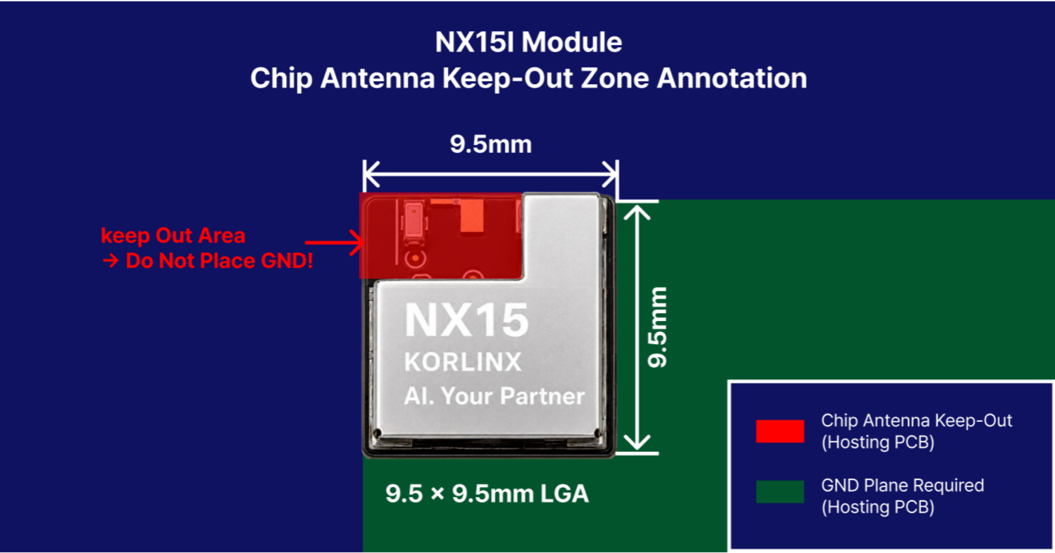
| Design Item | Recommendation |
|---|---|
| Antenna placement | Place the antenna side near the host PCB edge or corner |
| Keep-out area | Do not place copper, GND, signal traces, vias, or components in the antenna clearance area |
| Ground plane | Use a continuous ground plane where practical; no minimum area is specified because KORLINX has not validated a numeric host-PCB requirement |
| Ground quality | Avoid slots or splits in the ground plane near the RF area |
| Conductive objects | Keep batteries, shields, connectors, cables, and metal parts away from the antenna area |
| Enclosure | Verify RF performance with the final enclosure material and mechanical structure |
NX15i Antenna Reference Values
| Parameter | Value / Guideline |
|---|---|
| Operating Frequency | 2400–2500 MHz |
| Antenna Impedance | 50 Ω nominal |
| VSWR | < 2.0 : 1 reference value |
| Peak Gain | 1.1 dBi reference value |
| Average Total Efficiency | 49% reference value |
| Chip Antenna Size | 1.6 × 0.8 × 0.4 mm |
| Recommended Placement | Host PCB edge or corner |
:::note Source and scope The values above are Abracon antenna-component and evaluation-layout references. They are not measured NX15 module or final-product performance. Final RF performance depends on the host PCB, enclosure, and installation. :::
NX15E External Antenna / 50 Ω RF Interface
| Parameter | Requirement / Reference | Notes |
|---|---|---|
| RF Connector | On-module u.FL / UMCC | Use a compatible 50 Ω mating cable / pigtail |
| External Antenna Impedance | 50 Ω nominal | Use a 2.4 GHz antenna with 50 Ω feed impedance |
| Operating Band | 2400–2483.5 MHz | BLE / IEEE 802.15.4 operation |
| Reference Antenna | TE Connectivity 2108923 Series | Manufacturer reference; exact certified suffix must be confirmed |
| Reference VSWR | < 1.6 : 1 @ 2.4–2.5 GHz | TE Connectivity manufacturer data |
| Reference Peak Gain | 2.3 dBi @ 2.4 GHz | TE Connectivity manufacturer data |
| Coaxial Cable | 50 Ω | Keep the cable as short as practical |
| Host PCB RF Trace | Not required | RF path terminates at the on-module RF connector |
| Antenna Placement | Clear of metal / enclosure obstructions | Final enclosure and cable routing can affect RF performance |
The NX15E Series provides an on-module u.FL / UMCC-compatible 50 Ω RF connector for an external 2.4 GHz antenna.
This option is useful when the antenna must be placed away from the main PCB, outside an enclosure, or in a location with better RF exposure.
NX15E External Antenna Guidelines
| Design Item | Recommendation |
|---|---|
| RF connector | Use a compatible u.FL / UMCC 50 Ω mating cable or pigtail |
| Antenna impedance | Use a 50 Ω nominal 2.4 GHz antenna |
| Operating band | Use an antenna suitable for BLE / IEEE 802.15.4 operation |
| Coaxial cable | Keep the cable as short as practical |
| Cable routing | Avoid routing the cable over noisy digital circuits, switching power stages, or large metal structures |
| Antenna placement | Keep the antenna clear of metal and enclosure obstructions |
| Verification | Verify RF performance and regulatory compliance with the final antenna, cable, enclosure, and installation |
External Antenna Selection
When selecting an external antenna for NX15E, check the following:
- Frequency range
- 50 Ω feed impedance
- VSWR
- Gain
- Efficiency
- Connector type
- Cable length
- Enclosure position
- Regulatory and certification requirements
:::caution KC-certified antenna configuration Antennas cannot be added arbitrarily to the KC-certified configuration. Before using a customer-requested or alternative antenna, contact KORLINX so that we can confirm whether it can be registered under the KC certification and identify the required review, testing, registration, or certification procedure. :::
The 2108923-series values are sourced from TE Connectivity's antenna data. Manufacturer data does not establish NX15 module performance or KC approval for every series suffix.