
How to Use NX40 with nRF Connect SDK and Zephyr
This guide introduces nRF Connect SDK and Zephyr RTOS for DEV-NX40, using UF2 firmware upload over USB. It follows the technical progression of Nordic Developer Academy: understand the SDK, build an application, describe hardware, configure software, and add peripherals and concurrent tasks.
NX40 board support is provided by NX-Zephyr-Samples. Use board target nx40/nrf52840 with nRF Connect SDK v3.3.1, the tested release.
NX40 development platform illustration. Firmware is uploaded over USB through the UF2 bootloader.
Understand the platform
nRF Connect SDK combines Nordic software with Zephyr's kernel, drivers, and hardware descriptions. Its workspace contains several repositories, including nrf, zephyr, nrfxlib, and MCUboot. Available features depend on the selected device and application configuration; the SDK-wide protocol list is not a feature list for NX40.
The build uses separate inputs:
| Input or tool | Responsibility |
|---|---|
| C application | Runtime behavior |
| Devicetree | Hardware instances, connections, and properties |
| Kconfig | Software features and their settings |
| CMake | Build configuration |
| Ninja and compiler toolchain | Compilation and linking |
| west | Workspace and build/programming commands |
This separation lets application logic use board-defined devices without embedding connector pin numbers. See Nordic's SDK structure and content.
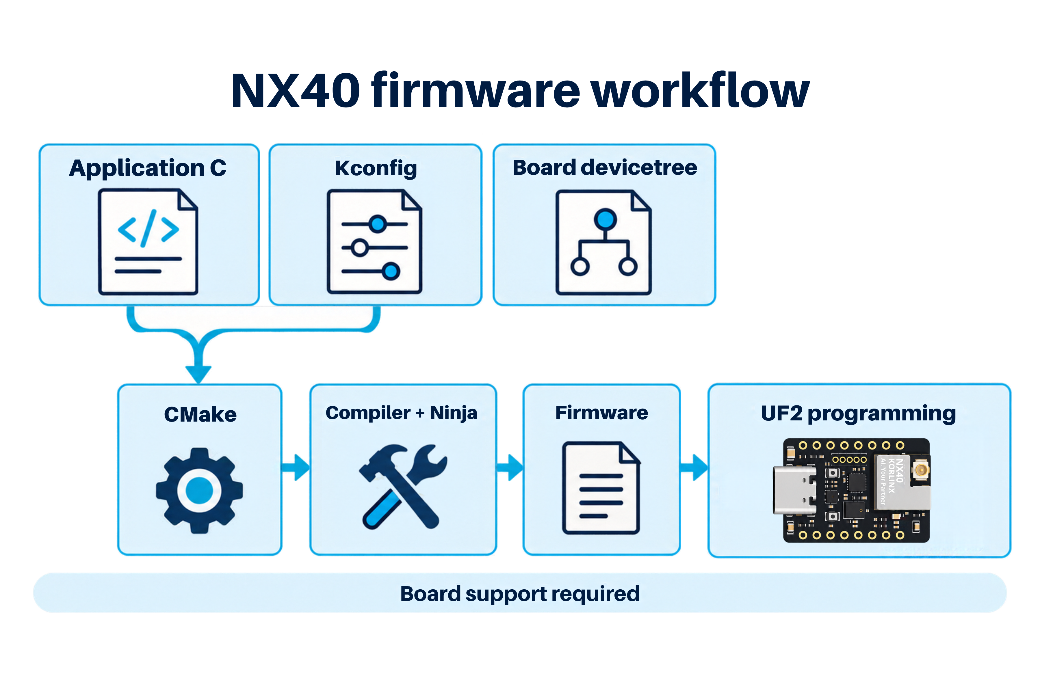
Application code, Kconfig, and board devicetree contribute to the firmware build, followed by UF2 programming over USB.
Supported host platforms
Nordic provides its VS Code development workflow for Windows, macOS, and Linux. Check the host requirements for the SDK release selected by the NX40 board package.
Record the operating system, SDK version, toolchain version, board-package revision, and UF2 bootloader version with each validated setup.
Before you begin
Required hardware
| Item | Requirement |
|---|---|
| Development board | DEV-NX40 with a matching Zephyr board definition |
| Bootloader | KORLINX UF2 bootloader installed on the board |
| USB cable | Data-capable cable connected to the board's native USB interface for UF2 upload |
| Optional console connection | Board-supported UART bridge or firmware-enabled USB CDC connection |
A bare NX40 module additionally needs a carrier with power, native USB access, the UF2 bootloader, and the required application circuitry. See Dev Kit Hardware and the module pin map.
Required software
- Visual Studio Code and Nordic's nRF Connect for VS Code Extension Pack.
- An nRF Connect SDK release and its matching toolchain.
- NX40 board support compatible with that release.
- Host USB support for the bootloader's mass-storage drive; serial drivers if using a UART console.
Install nRF Connect for VS Code
- Install Visual Studio Code for your operating system.
- Open Extensions from the Activity Bar.
- Search for nRF Connect for VS Code and select the extension pack published by Nordic Semiconductor.
- Select Install, then reload VS Code if prompted.
- Open nRF Connect from the Activity Bar.
The pack provides these tools:
| Extension | Purpose |
|---|---|
| nRF Connect | SDK management, building, flashing, and debugging |
| nRF DeviceTree | Hardware-description editing and visualization |
| nRF Kconfig | Software-configuration editing |
| nRF Terminal | Serial and RTT terminal access |
Follow Nordic's installation exercise for release-specific SDK prerequisites. The NX40 UF2 upload procedure uses the bootloader's USB drive.
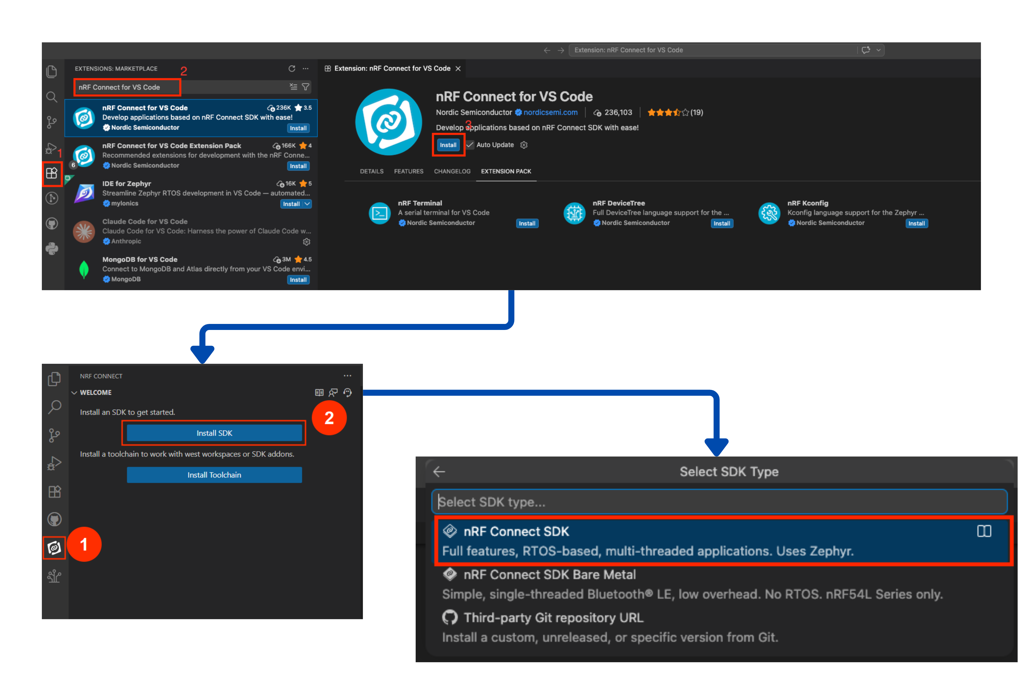
Install the Nordic extension, then select Install SDK and the Zephyr-based nRF Connect SDK option.
Install the SDK and toolchain
- In the nRF Connect welcome view, select Install SDK.
- If prompted for SDK type, select nRF Connect SDK for the Zephyr-based workflow.
- Select the release supported by the NX40 board package and install its matching toolchain.
- Confirm installation in Manage SDKs and open a terminal associated with that SDK environment.
Installing the extension alone does not install the SDK. Install Toolchain is for toolchain-only setups, such as an existing west workspace. UI labels can vary by version.
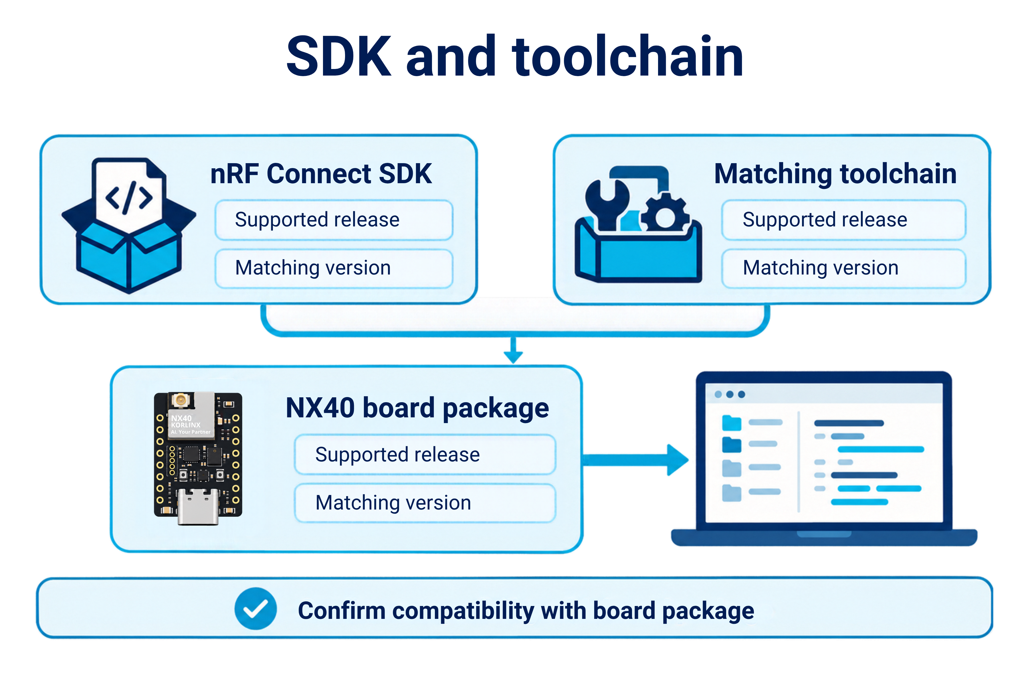
Match the SDK and toolchain to the board package. The tested release is nRF Connect SDK v3.3.1.
Select the NX40 hardware definition
The NX40 board definition is provided as a Zephyr module by the NX-Zephyr-Samples repository. See Get the samples to install it. It defines:
| Board setting | NX40 board definition |
|---|---|
| Target | nx40/nrf52840, tested with nRF Connect SDK v3.3.1 |
| LED | led0 is the red user LED on P0.11, active low |
| Clock sources | 32.768 kHz crystal for the low-frequency clock |
| Console | Native USB CDC ACM, started by the board at boot |
| Flash layout | Application at 0x26000 (792 KB), after the SoftDevice region used by the KORLINX UF2 bootloader |
| UF2 output | Enabled by the board, family ID 0xADA52840 |
| Module variant | External flash (32 Mbit) enabled; disable its node with an overlay on a no-flash module |
Do not substitute nrf52840dk/nrf52840 just to make compilation succeed. A build can succeed while using incompatible pins or flash settings.
Prepare the UF2 USB connection
- Connect DEV-NX40 to the computer through its native USB interface using a data-capable cable.
- Enter UF2 bootloader mode using the reset-button sequence documented for the installed KORLINX bootloader.
- Confirm that a removable USB drive appears in the host file manager.
- Keep the board connected while preparing the UF2 application image.
Use the drive name reported by your board; it depends on the installed bootloader. The FTDI USB-to-UART bridge provides a serial console, while UF2 upload uses the native USB bootloader's mass-storage interface.
Use the NX40 board package's application flash layout and UF2 settings. Generating a .uf2 file alone does not make an arbitrary Zephyr image compatible with the installed bootloader. Preserve the bootloader and its reserved flash regions.
Build your first application
- In nRF Connect for VS Code, create an application by copying a sample.
- Select
zephyr/samples/basic/blinkyfrom the installed SDK. - Save the copy as
nx40_blinkyoutside the SDK's sample directory. - Add a build configuration and select the installed SDK, matching toolchain, and exact NX40 board target.
- Apply only the overlays and configuration files required by the NX40 board package.
Nordic's first build exercise demonstrates the sample-copy and build-configuration workflow.
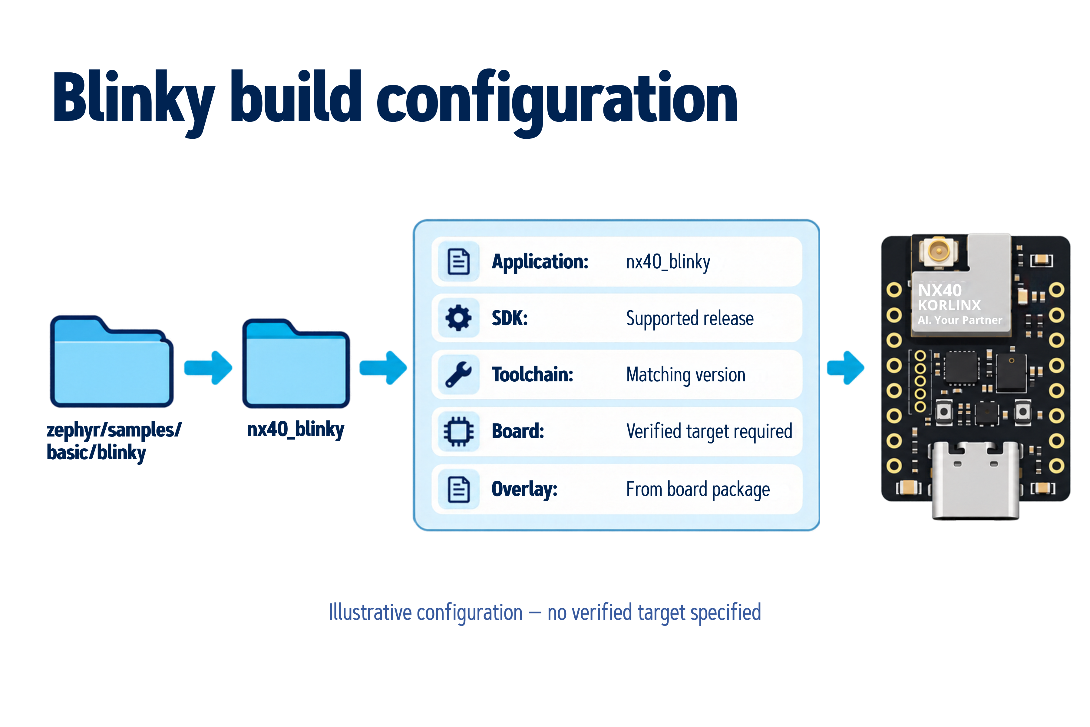
Illustrative build configuration. Select the SDK, toolchain, and verified NX40 target supplied by the board package.
Upload over USB
- Enter UF2 bootloader mode again if the removable drive is no longer visible.
- Copy the generated application
.uf2file to that drive using the host file manager. - Wait for the copy to finish. The bootloader programs the application and normally restarts the board; its USB drive may disappear.
- If the board remains in bootloader mode, follow its documented reset procedure to start the application.
- Check the expected application behavior, such as the Blinky LED.
Repeat the build and copy steps after changing the application. Copy the generated UF2 artifact; renaming a .hex or .bin file to .uf2 does not convert it.
NX40 sample applications
The NX-Zephyr-Samples repository contains the NX40 board definition and ready-to-build samples for the on-board peripherals and Bluetooth LE. The repository is a Zephyr module, so you can keep it outside your nRF Connect SDK workspace.
Get the samples
Clone the repository next to your nRF Connect SDK workspace:
git clone https://github.com/KORLINX/NX-Zephyr-Samples
The commands below refer to the path of this clone as <repo>.
Build and upload a sample
-
Open a terminal in the nRF Connect SDK environment and change to the SDK workspace directory.
-
Build the sample. Pass the repository as an extra Zephyr module so the build can find the NX40 board:
west build -p always -b nx40/nrf52840 -d build/hello <repo>/samples/hello -- -DZEPHYR_EXTRA_MODULES=<repo> -
Upload
build/hello/hello/zephyr/zephyr.uf2as described in Upload over USB, or let west copy it to the bootloader drive:west flash -d build/hello -r uf2 -
Open the DEV-NX40 USB serial port to see the output.
west flash -r uf2 can report a FileNotFoundError after the copy, because the bootloader resets as soon as it receives the image. The image is programmed when DEV-NX40 restarts and its USB serial port reappears.
Samples built from this repository reboot into the bootloader when the USB serial port is opened at 1200 baud and closed, so you do not need to press reset for the next upload. On Linux: stty -F /dev/ttyACM0 1200.
Available samples
| Sample | What it shows | Status on DEV-NX40 |
|---|---|---|
| hello | Console output with printk and the logging subsystem | Verified |
| uart | Interrupt-driven UART receive and echo on the console port | Verified |
| dmic | PDM microphone capture with the DMIC API | Verified |
| qspi_flash | Erase, write and verify of the 32 Mbit external flash with the flash API | Verified |
| direct_test_mode | Bluetooth LE Direct Test Mode for RF testing over USB serial | Verified |
| dht_polling | Temperature and humidity from the SHTC3 with the sensor API | Validation in progress |
| lsm6dso | Accelerometer and gyroscope data from the 6-axis IMU | Validation in progress |
| gatt | Bluetooth LE peripheral with a custom GATT service and notifications | Validation in progress |
| rssi_power_control | Connection RSSI and LE Power Control between two boards (central and peripheral) | Validation in progress |
| nrf_dm | Distance measurement between two boards | Validation in progress |
Each sample folder contains a README.rst with its requirements, build command, and expected behavior.
The qspi_flash sample erases the entire external flash. Do not run it on a board whose external flash contents you need to keep.
Onboard LED
Zephyr's Blinky sample uses the led0 alias to select a physical LED. Use the verified NX40 board definition to configure that alias.
Build and run Blinky
- Build and upload Blinky as described in Build your first application.
- Observe the user LED assigned to
led0; it should alternate between on and off. - Change
SLEEP_TIME_MSin the sample, rebuild, and upload the new UF2 file. Confirm that the interval changes.
How the LED is selected
The sample resolves an alias into a GPIO specification:
#define LED0_NODE DT_ALIAS(led0)
static const struct gpio_dt_spec led = GPIO_DT_SPEC_GET(LED0_NODE, gpios);
Trace led0 to the board's LED node. Its gpios property supplies the controller, pin number, and polarity. For an active-low LED, the devicetree flag makes the GPIO API interpret the active state correctly.
Expected result
The red user LED (led0, P0.11, active low) blinks at the configured interval. Power and charging indicators do not verify Blinky.
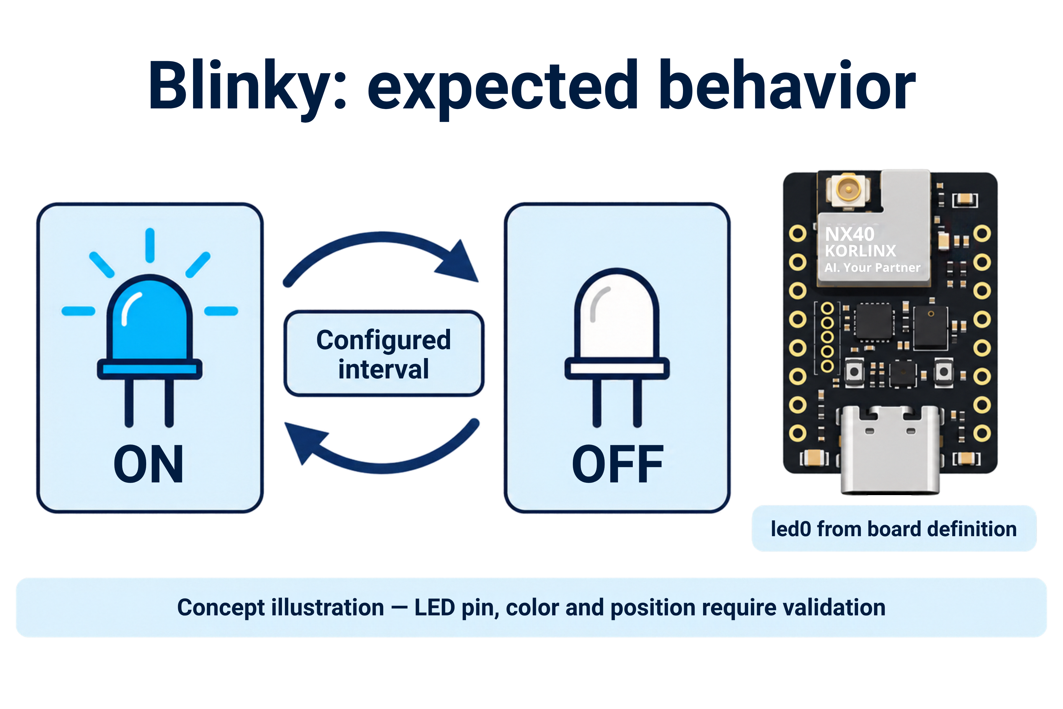
Expected Blinky behavior, not a hardware test capture. On DEV-NX40 the LED mapped to led0 is the red user LED.
Describe hardware with devicetree
A devicetree is a hierarchy of hardware nodes and properties. A node label identifies a node in source; an alias provides a name that portable application code can look up. Board files describe assembled hardware, while SoC include files describe the chip's peripherals. Read Nordic's Devicetree lesson.
Use the GPIO API
Nordic's GPIO Generic API lesson introduces this sequence:
- Retrieve a
gpio_dt_specwithGPIO_DT_SPEC_GET(). - Check the controller using
gpio_is_ready_dt(). - Configure the pin with
gpio_pin_configure_dt()and check its return value. - Read or drive the pin using the GPIO API.
Logical active/inactive operations honor the devicetree polarity. An active-low LED therefore needs the correct flag in its hardware definition. After Blinky, apply the same approach to the NX40 user button with its verified input and pull configuration.
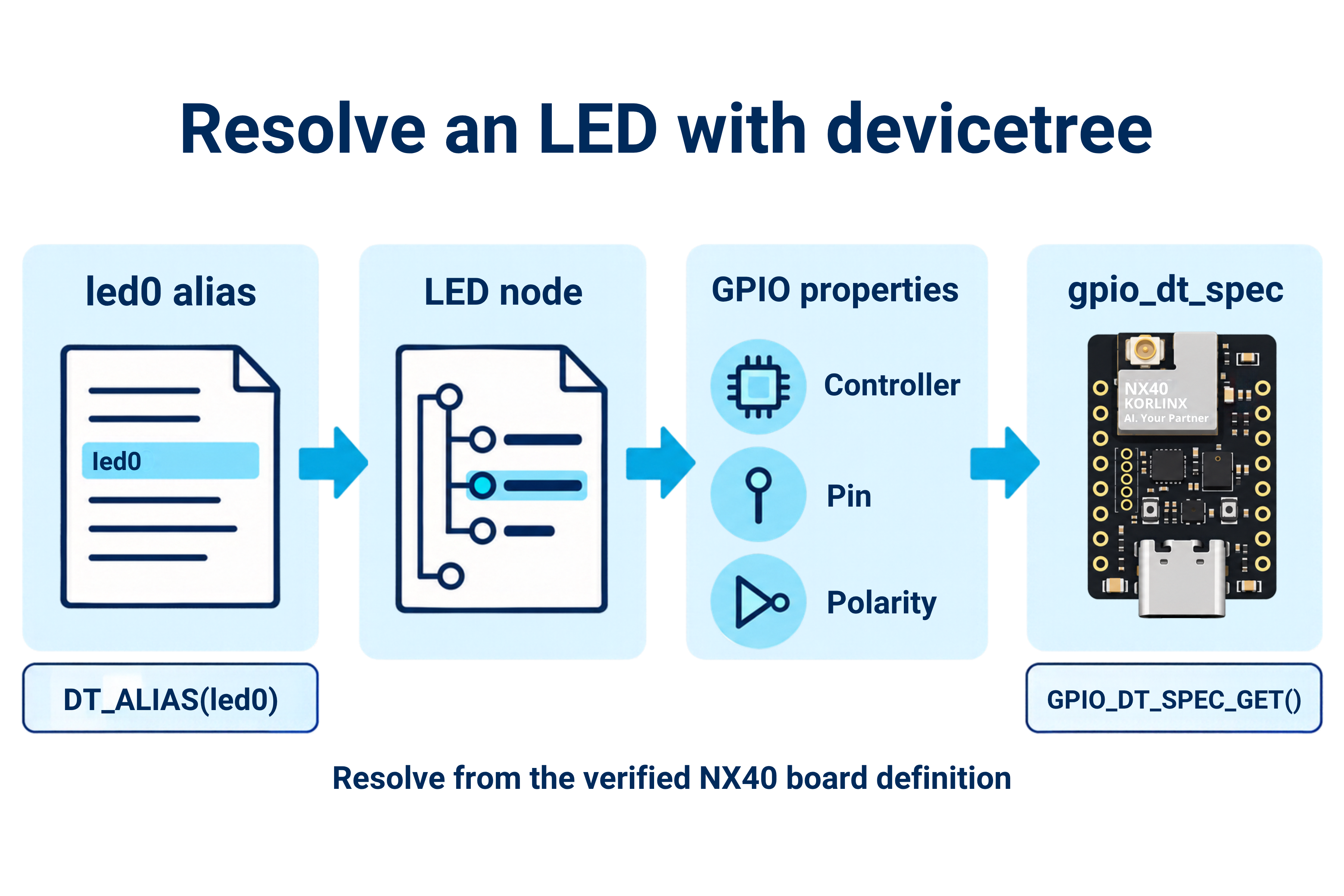
The led0 alias resolves to an LED node whose GPIO properties define the controller, pin, and polarity.
Configure application features
Understand the application files
| File | Purpose |
|---|---|
src/main.c | Application logic |
CMakeLists.txt | Build definition and source list |
prj.conf | Application Kconfig options |
| Board devicetree and overlays | Hardware nodes, pin routing, and aliases |
Zephyr separates application behavior from hardware description. See Application Development for configuration-file and overlay handling.
Arduino's LED_BUILTIN does not define Zephyr's led0 alias. See the Blinky sample requirements.
Kconfig and prj.conf
Application configuration contains CONFIG_ assignments. For example, CONFIG_GPIO=y enables GPIO support. Board defaults and application settings contribute to the final configuration; dependencies determine which options can actually be enabled.
Inspect the generated .config for the application image when an option behaves unexpectedly. Change the source configuration and rebuild, rather than editing generated output. Nordic explains this in Configuration files.
Devicetree overlays
Use application overlays for hardware changes specific to an example. An overlay changes selected nodes or properties without rewriting the shared board files. Enabling a node and enabling its driver are separate tasks: review both devicetree and Kconfig.
When rerouting a Nordic peripheral, check its pinctrl configuration, including applicable default and sleep states. Confirm the selected overlay in the build log and inspect the generated zephyr.dts. The output is inside the application's image build directory, which can be nested when using sysbuild.
See Nordic's overlays and build systems lesson.
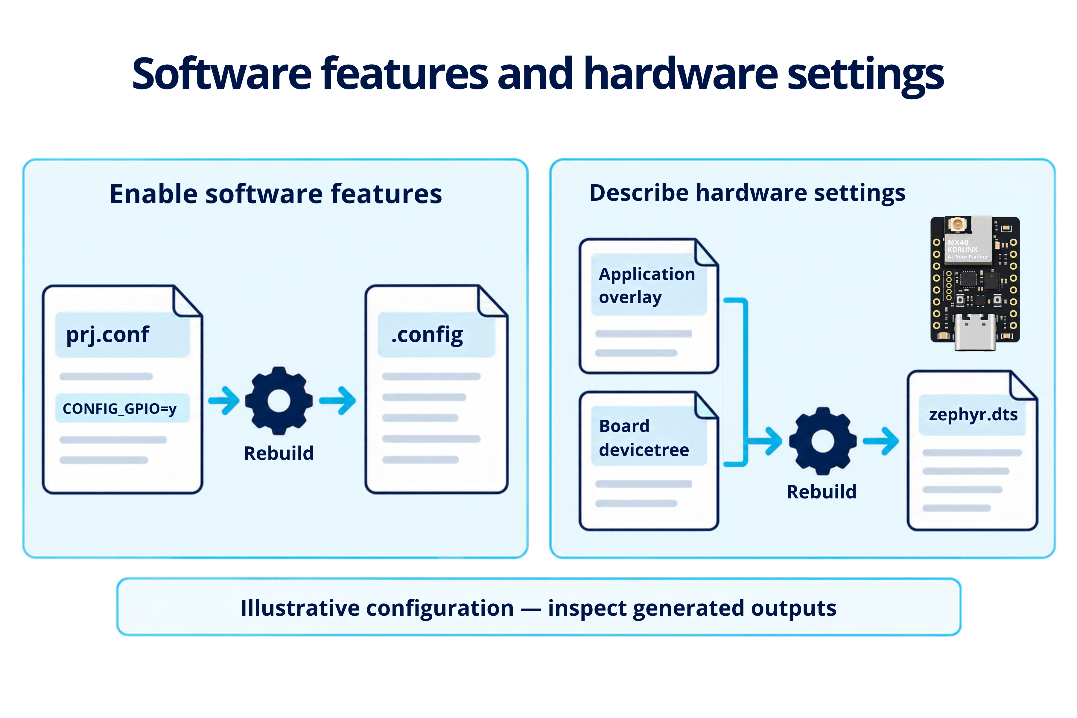
Software configuration produces .config; board devicetree and overlays produce the resolved zephyr.dts.
Console output and logging
Copy zephyr/samples/hello_world into a separate application. Build and upload its UF2 firmware with the same board target and its documented console configuration.
| Console path | How to observe it |
|---|---|
| Hardware UART | Open the connected bridge's serial port at the configured baud rate |
| RTT (optional debugging) | Requires a separate debug probe and firmware configured for RTT; UF2 upload itself does not provide RTT |
| Native USB CDC | Default console of nx40/nrf52840; open the DEV-NX40 USB serial port |
Reset the board after opening the viewer to capture startup output. Hello World should print a greeting identifying the configured board. Do not assume that an FTDI port receives native USB CDC output or that Arduino's serial settings carry over.
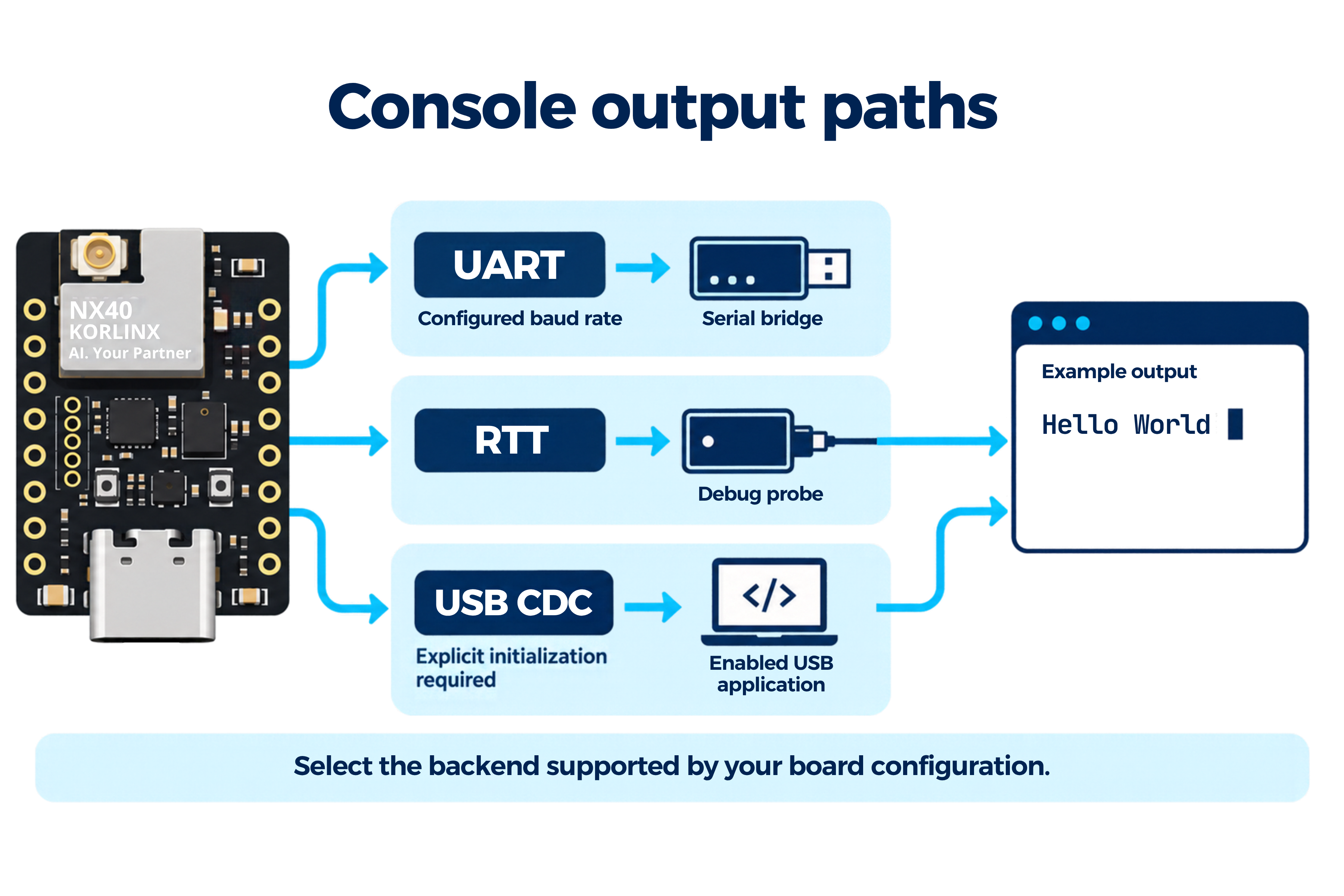
Alternative console paths; select the backend enabled in your firmware. The displayed output is illustrative.
Choose a logging backend
Use printk() for a simple console check. For ongoing diagnostics, Nordic teaches the logger module with severity levels, filtering, deferred processing, and multiple backends. Enable logging with CONFIG_LOG=y, register an application module, and select a backend supported by the board configuration.
A log message being compiled into firmware does not guarantee that it reaches a connected serial port. UART and RTT have different transport requirements. See the Logger module lesson.
Troubleshooting
| Symptom | What to check |
|---|---|
| NX40 target is unavailable | Install the matching board package and check its board-root/module discovery instructions |
led0 or GPIO build error | Confirm the alias, referenced LED node, and driver configuration |
| Build uses unexpected pins | Inspect the generated devicetree and selected overlays; use a pristine build after changing targets |
| UF2 USB drive does not appear | Check the data cable, native USB connection, installed bootloader, and its documented entry sequence |
No .uf2 file after building | Check CONFIG_BUILD_OUTPUT_UF2, the selected build directory, and any sysbuild image subdirectories |
| UF2 copy completes but application does not start | Check the board target, UF2 family ID, application start address, reserved flash regions, and bootloader compatibility |
| Flash succeeds but no LED toggles | Confirm LED assignment, polarity, image layout, and reset behavior |
| No console output | Check the selected backend, physical routing, port, and UART baud rate |
| Bootloader is missing or damaged | Follow the KORLINX bootloader recovery procedure before resuming UF2 uploads |