
NX40 Module Antenna
| Model type | Antenna path | Use case |
|---|---|---|
| NX40i | Integrated ceramic chip antenna | Compact host products with a clear antenna area |
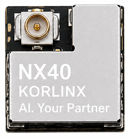
| NX40E | On-module external-antenna connector | Products that need antenna placement away from the host PCB |
Caution: RF performance depends on the host PCB, enclosure, ground structure, nearby metal, cable routing, and installation. Verify the completed product through RF testing and the required regulatory process.
NX40i Integrated Antenna
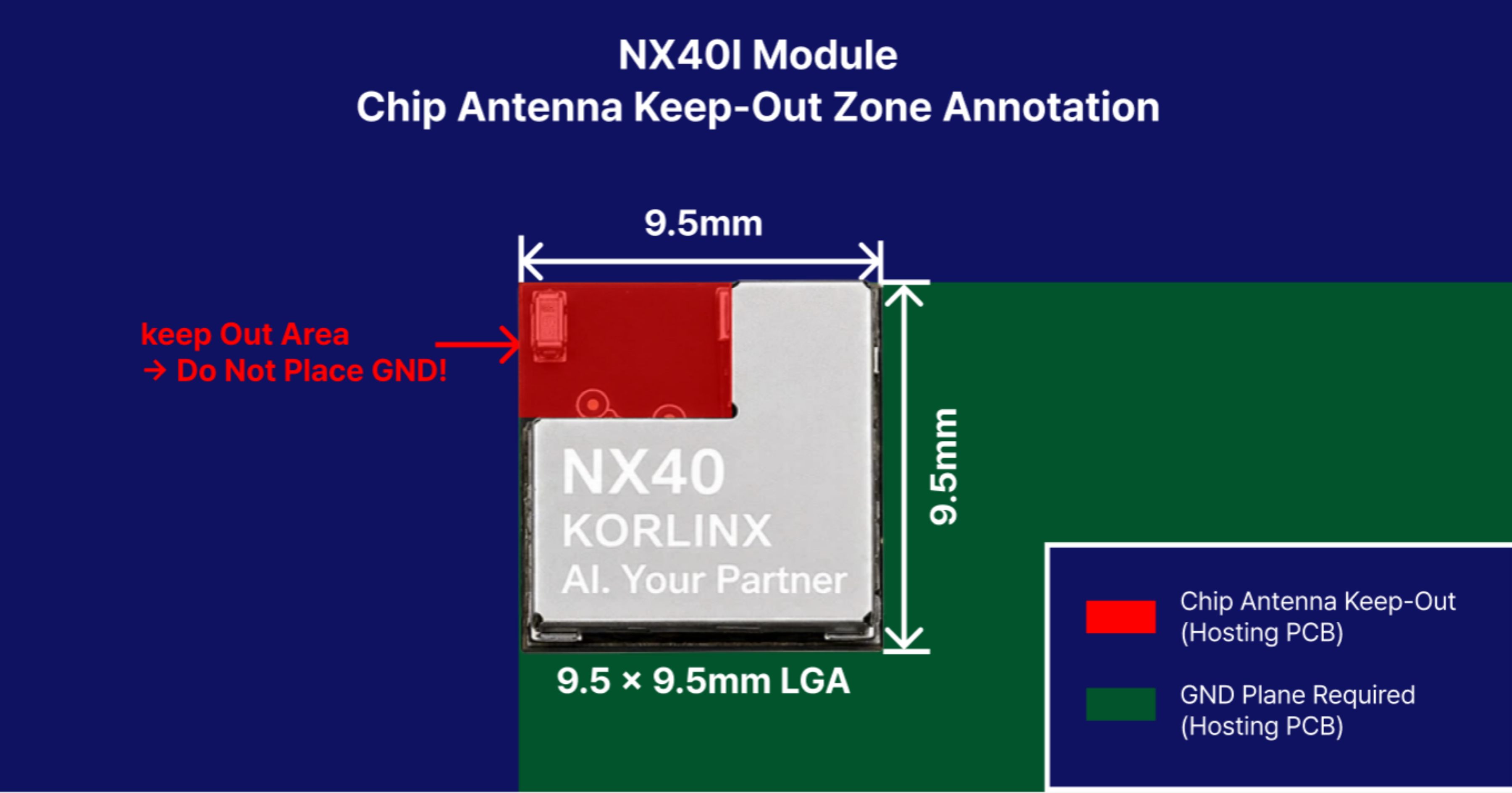
The supplied NX40i schematic identifies an Abracon AANI-CH-0133-Q ceramic antenna. The following values come from the Abracon AANI-CH-0133-Q datasheet and describe the antenna component on Abracon's evaluation layout. They do not describe the completed NX40 module or customer host product.
| Component parameter | Abracon reference value | Publication status |
|---|---|---|
| Operating frequency | 2400–2500 MHz | Component reference |
| Impedance | 50 Ω nominal | Component reference |
| VSWR | < 2.0:1 | Evaluation-board reference |
| Peak gain | 1.1 dBi | Evaluation-board reference |
| Average total efficiency | 49% | Evaluation-board reference |
| Antenna size | 1.6 × 0.8 × 0.4 mm | Component dimension |
| Local clearance | 5 × 3 mm | Abracon evaluation-layout reference |
Host Layout Guidance
- Place the antenna end near an outer edge or corner of the host PCB.
- Keep copper, ground, signal traces, vias, components, batteries, shields, and cables outside the antenna clearance region.
- Maintain a continuous low-impedance ground connection beneath the module ground region.
- Test the antenna with the final enclosure, battery, display, cables, and mounting hardware installed.
KORLINX does not specify a minimum host-PCB ground-plane area because a numeric requirement has not been validated on NX40 hardware.
NX40E External Antenna / 50 Ω RF Interface
| Parameter | Requirement / reference | Notes |
|---|---|---|
| RF connector | On-module micro-coax connector | Exact manufacturer and part number pending approval |
| External antenna impedance | 50 Ω nominal | Use a 2.4 GHz antenna with a 50 Ω feed |
| Operating band | 2400–2483.5 MHz | Bluetooth LE / IEEE 802.15.4 use depends on software and regional configuration |
| Reference antenna family | TE Connectivity 2108923 Series | Manufacturer reference; exact certified suffix must be confirmed |
| Reference VSWR | < 1.6:1 at 2.4–2.5 GHz | TE Connectivity manufacturer data |
| Reference peak gain | 2.3 dBi at 2.4 GHz | TE Connectivity manufacturer data |
| Coaxial cable | 50 Ω | Keep the cable as short as practical |
| Host PCB RF trace | Not required | RF terminates at the on-module connector |
External Antenna Selection
Check frequency range, impedance, VSWR, gain, efficiency, connector, cable length, placement, enclosure effects, and certification scope. The 2108923-series reference values come from TE Connectivity's antenna data; they are not measured NX40 performance.
:::caution KC-certified antenna configuration Antennas cannot be added arbitrarily to the KC-certified configuration. Before using a customer-requested or alternative antenna, contact KORLINX so that we can confirm whether it can be registered under the KC certification and identify the required review, testing, registration, or certification procedure. :::