
KSE-91A Quick Start
The KSE-91A is a cellular communication module based on the nRF9151 platform. This guide helps you connect the module, understand the LCD screen flow, use the button actions, check Location, open Diagnostics, and configure the host communication interface.
Quick Start Flow
Use the following flow for first-time operation.
| Step | Action | Expected Result |
|---|---|---|
| 1 | Connect LTE/GNSS antennas | Antennas are securely connected to the SMA connectors |
| 2 | Prepare the Nano USIM | SIM is ready for cellular network access |
| 3 | Connect USB Type-C or host connector | PC or host equipment can communicate with the module |
| 4 | Apply power | Module starts and shows startup screens |
| 5 | Wait for Connected | Module attaches to the cellular network |
| 6 | Short press from Home / Connected | Opens the Location screen |
| 7 | Long press from Home / Connected or Location | Opens Diagnostics |
| 8 | Hold the button while powering on | Opens Interface Configuration |
For normal use, start from the Home / Connected screen. Use short press to switch to Location and long press to open Diagnostics.
Hardware Overview
The KSE-91A hardware provides external LTE/GNSS antenna connectors, a USB Type-C connector, a 12-pin host connector, an LCD display, and button controls for screen navigation and interface configuration.
Antenna Connectors
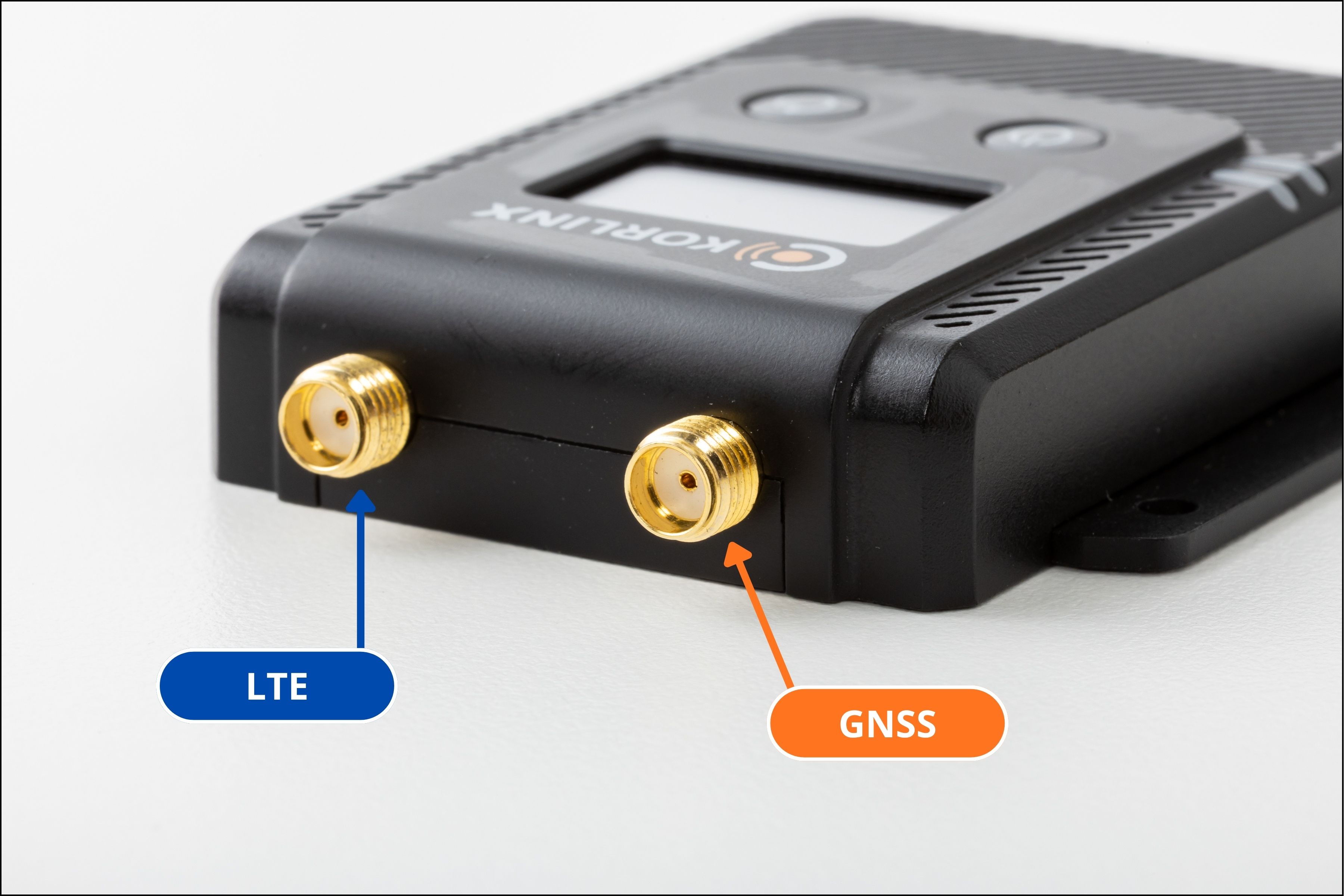
| Part | Description |
|---|---|
| SMA antenna connectors | Used for external LTE and GNSS antenna connection |
| Antenna type | SMA type external LTE and GNSS antenna |
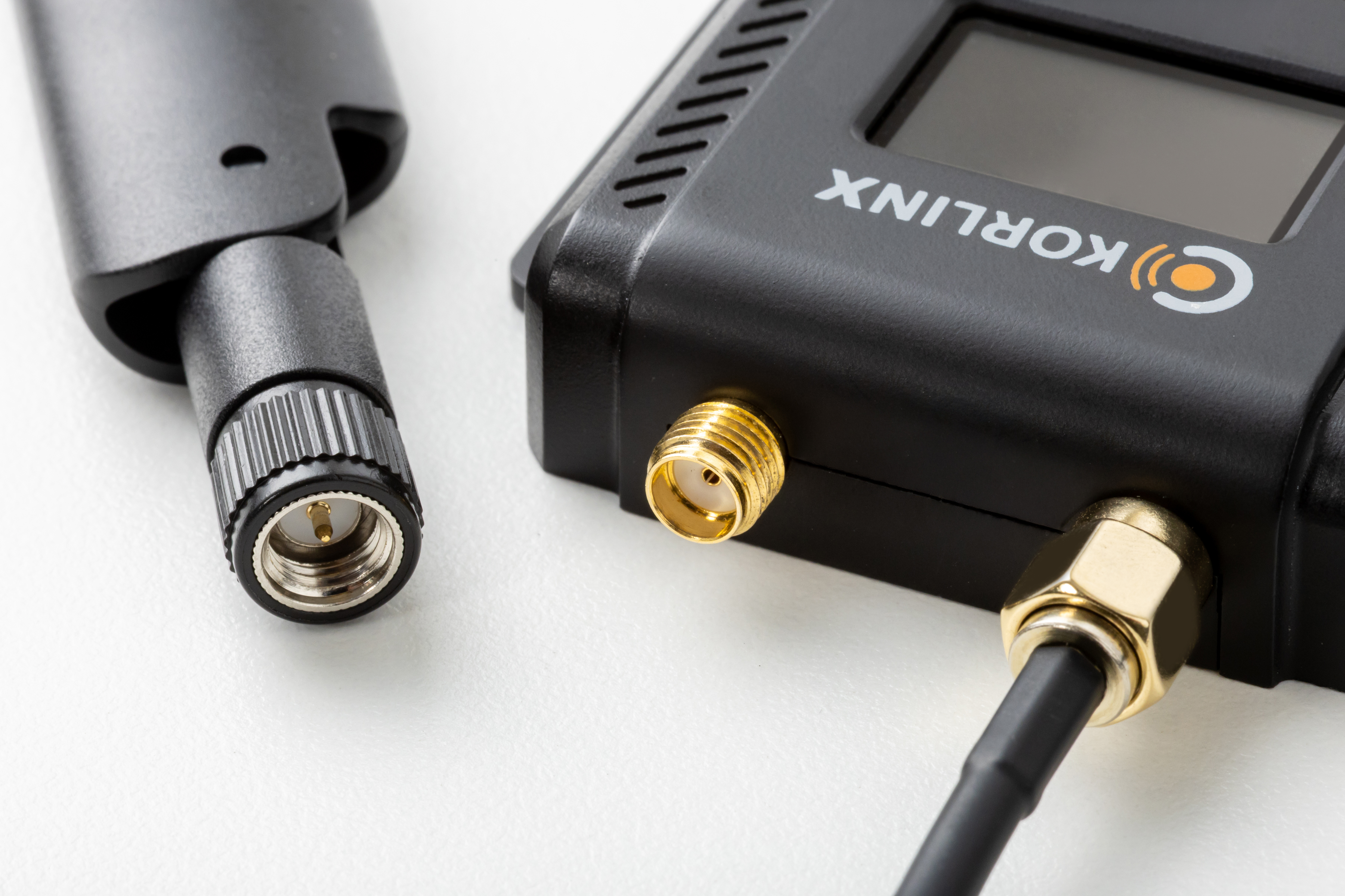
Connect the LTE/GNSS antennas before powering on the module. A missing or loose antenna may cause weak signal, slow connection, or GPS fix issues.
USB Type-C Connection
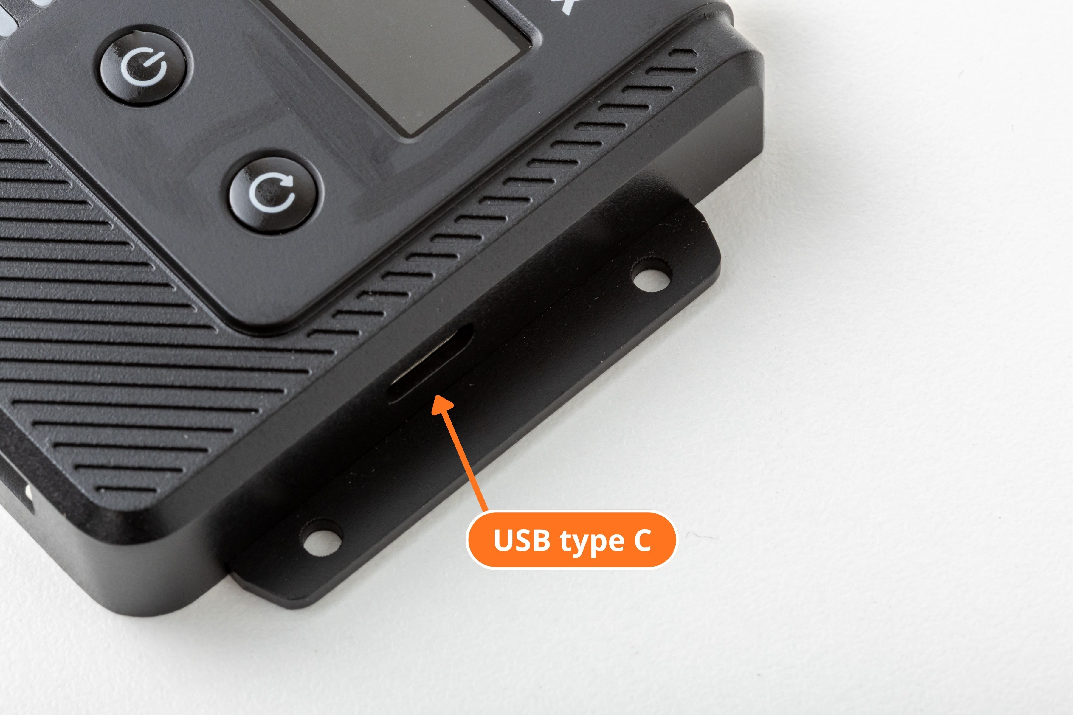
The KSE-91A supports communication with a PC through the USB Type-C connector.
| Item | Description |
|---|---|
| Connector | USB Type-C |
| Usage | Connect the KSE-91A module to a PC for communication |
| Location | Side connector on the KSE-91A enclosure |
To use USB Type-C, connect the KSE-91A to the PC using a USB Type-C cable, then open the corresponding serial or communication port on the PC.
Keep the latest catalog as the primary source for product specifications. The USB Type-C connection description is provided as a connection reference.
Host Connector
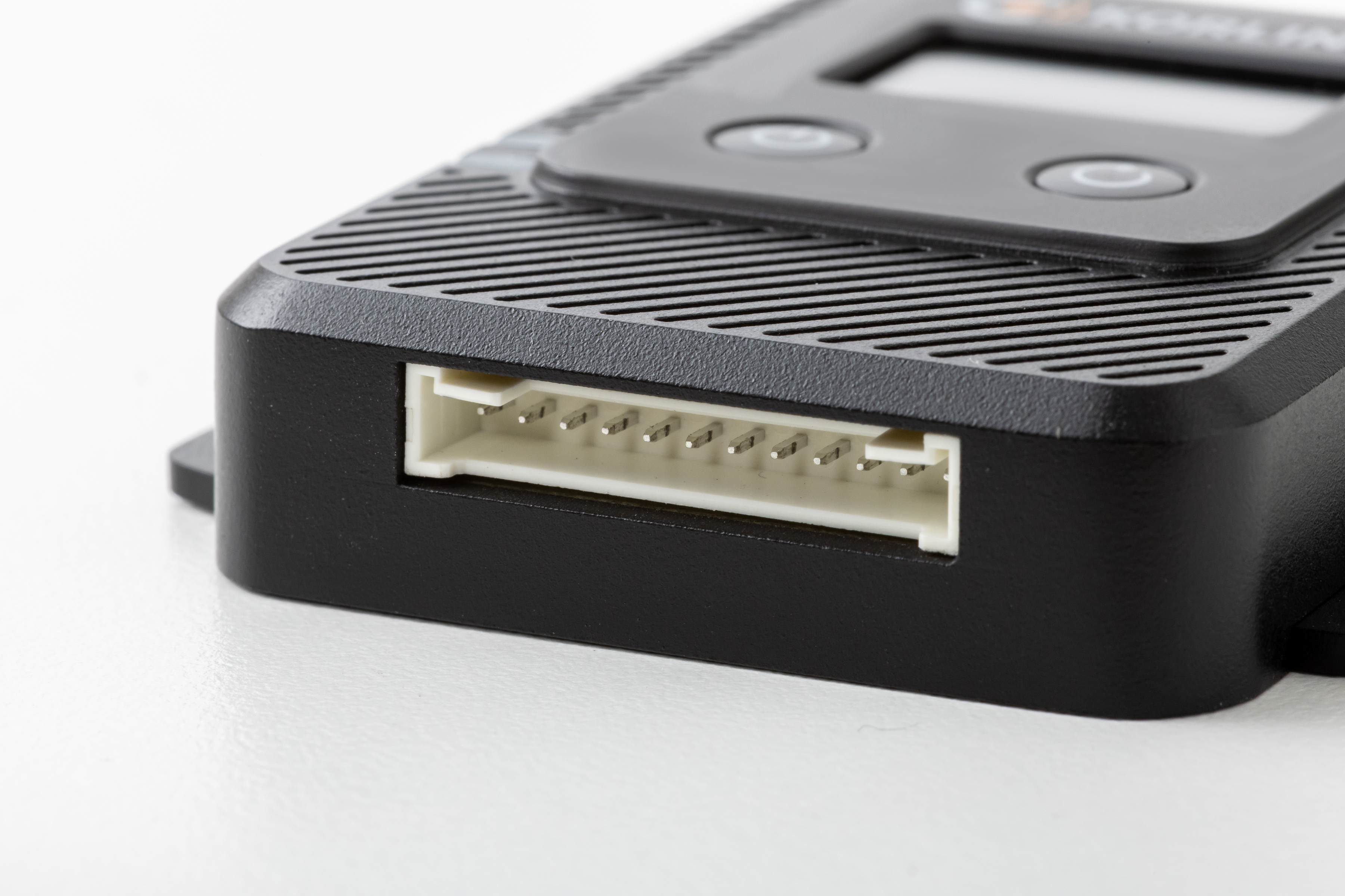
| Part | Description |
|---|---|
| Host connector | 12-pin connector |
| Connector pitch | 2 mm |
| Supported host interfaces | UART, RS485, RS232, USB-C depending on model |
Pin List
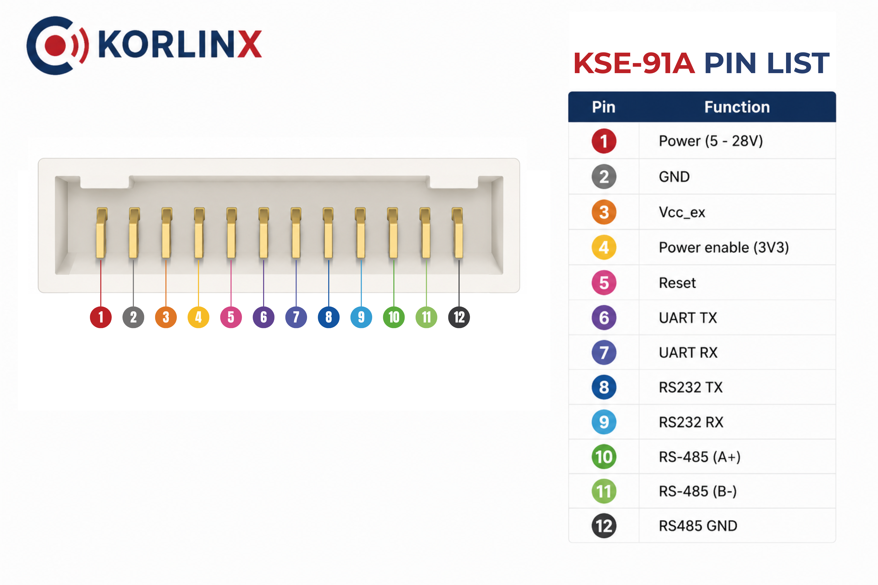
Button and Reset Overview
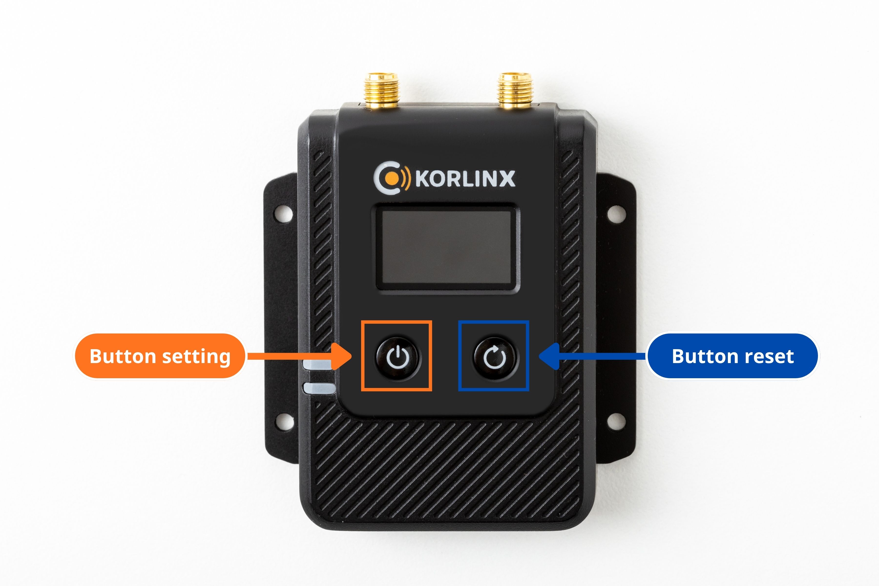
| Control | Description |
|---|---|
| Setting button | Used for screen navigation and interface configuration |
| Reset button | Press and hold for 7 seconds to reset the module |
Specification
General
| Item | Specification |
|---|---|
| Model name | KSE-91A |
| Product type | External type industrial LTE-M product |
| Display | 1.06" IPS Display |
| MCU | 64 MHz Arm Cortex-M33 |
| Memory | 1 MB flash + 256 KB RAM, EXT 4 MB flash |
| Modem | Multimode LTE-M / NB-IoT modem |
| Protocol | MQTT, CoAP, HTTP, LwM2M |
| Control | AT-COMMAND |
| Firmware update | FOTA via LTE |
| GNSS | Supported |
| USIM | Nano USIM, Supported Global and KT (scheduled) |
| Antenna | SMA type external LTE and GNSS antenna |
| Input voltage | 5–28V DC |
| Connector | 12-pin connector, pitch 2 mm |
| Frequency | 700–2200 MHz LTE band support |
| LTE Cat-M1 bands | B3, B5, B8 |
| LTE NB-IoT bands | B3, B5 |
| Size | 69.4 × 46.7 × 15.9 mm |
| Certification | KC |
| Security | Arm TrustZone + Arm CryptoCell 310 |
Interface Variants
| Model | Interface | Control |
|---|---|---|
| KSE-91A-UART | UART, USB-C | AT-COMMAND (UART) |
| KSE-91A-485 | UART, RS485, USB-C | AT-COMMAND (UART, RS485) |
| KSE-91A-232 | UART, RS232, USB-C | AT-COMMAND (UART, RS232) |
| KSE-91A | UART, RS485, RS232, USB-C | AT-COMMAND (UART, RS485, RS232) |
Current Consumption
| Mode | Specification |
|---|---|
| Current consumption (Tx) | About 120 mA average in LTE-M mode, varies by band and output level |
| Current consumption (LP) | About 40 µA in PSM (power-saving mode) |
| eDRX @ 81.92 s | 60 µA in Cat-M1, 80 µA in Cat-NB1, UICC included |
Before You Start
Prepare the following items before using the KSE-91A.
| Item | Purpose |
|---|---|
| KSE-91A module | Main cellular communication device |
| LTE/GNSS antennas | Required for cellular and location-related operation |
| Nano USIM | Required for cellular network access |
| USB Type-C cable or host connector wiring | Used for PC or host equipment communication |
| Power source | Supplies power to the module |
| Serial terminal or host application | Used to send AT commands and check communication |
Do not power on the module until the required antenna and host/power connections are prepared.
Connect the Module
1. Connect the LTE/GNSS Antennas
Connect the external LTE/GNSS antennas securely to the SMA antenna connectors.
2. Prepare the Nano USIM
Prepare a Nano USIM that supports the intended LTE-M / NB-IoT network service.
If the SIM is missing or cannot be detected, the module shows the Check SIM screen during startup.
3. Connect USB Type-C or Host Interface
For PC communication, connect the module through USB Type-C.
For host equipment integration, connect the correct pins according to the selected host interface: UART, RS232, or RS485.
| Interface | Pins / Signals |
|---|---|
| UART | UART TX, UART RX, GND |
| RS232 | RS232 TX, RS232 RX, GND |
| RS485 | RS485 A, RS485 B, RS485 GND |
4. Apply Power
After the antenna, SIM, and communication connection are prepared, apply power to the module.
The LCD should show the startup sequence and then move toward the Connected screen if the network attach is successful.
Verify AT Command Communication
After the LTE/GNSS antennas, Nano USIM, host interface, and power connection are prepared, verify that the KSE-91A can respond to AT commands.
KSE-91A supports AT command control through the available host interface depending on the product model and selected interface configuration.
Basic Communication Check
Open the serial terminal or host application connected to the KSE-91A, then send a basic AT command:
AT
A normal AT command interface should return an OK response when the host communication path is working.
Startup and Connection Screens
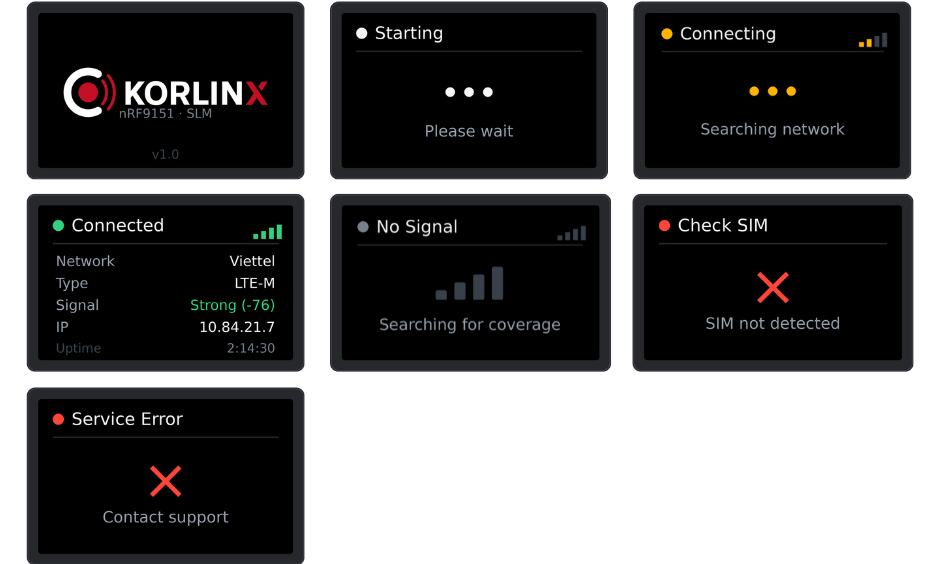
The module displays several screens during power-on and cellular network attachment.
| Screen | How It Appears | Meaning | User Action |
|---|---|---|---|
| Boot | Immediately after power-on | Module is powering up and shows product branding, platform, and firmware version | No action needed |
| Starting | After Boot | Modem is being initialized | Wait |
| Connecting | After Starting | Module is searching for and attaching to the mobile network | Wait; this may take up to about one minute |
| Connected | After successful network attachment | Module is online and attached to the network | Normal operating state |
| No Signal | Appears if no mobile coverage is available | The module cannot find coverage | Move the module or antenna to a better reception area |
| Check SIM | Appears if SIM is not detected | SIM card is missing or cannot be read | Power off, reseat SIM, then power on again |
| Service Error | Appears if service is refused or fails | Network was reached, but the connection failed | Check SIM plan/service and collect Diagnostics information |
The Connecting screen is normal during startup. Wait until the module reaches Connected or shows a clear fault screen.
🎉 You're Ready!
Welcome to KORLINX Cellular Module
You've completed the basic hardware connection and UART communication check.
From power wiring to your first AT command response — that's an important first step.
- ✅ Connected the LTE antenna
- ✅ Prepared the Nano USIM
- ✅ Connected power and ground correctly
- ✅ Wired the UART host interface
- ✅ Sent your first
ATcommand - ✅ Received an
OKresponse from the module
What's next?
Network Attach
Continue with LTE-M / NB-IoT network registration and signal checks.
GNSS Preparation
Prepare antenna placement and test location-related features.
Network Attach
Use AT commands to configure the modem and check cellular status.
Host Integration
Integrate the module with your MCU, host board, or application firmware.
Your module is now responding over UART. You can continue with network connection checks and product integration.
Home / Connected Screen
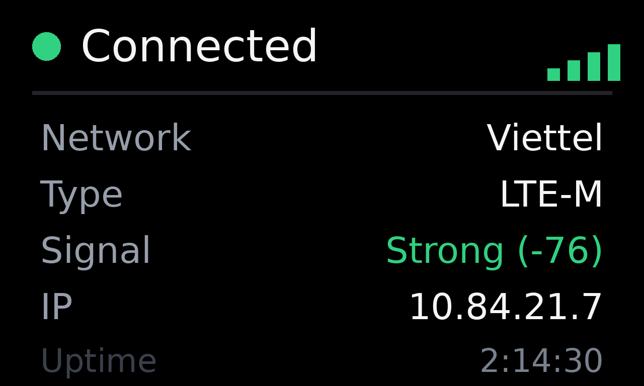
How to access this screen
The Home / Connected screen appears automatically after the module successfully attaches to the cellular network.
If you are on the Location screen, use a short press to return to Home / Connected.
What this screen shows
| Field | Meaning |
|---|---|
| Network | Mobile operator currently used |
| Type | Cellular connection type, such as LTE-M |
| Signal | Signal quality with technical value |
| IP | IP address assigned by the mobile network |
| Uptime | How long the module has been connected |
Action on this screen
| Action | Result |
|---|---|
| Short press | Switch to Location |
| Long press | Open Diagnostics |
Button Operation and Screen Actions
KSE-91A uses a single button. The button behavior depends on the screen currently shown on the LCD.
| Action | How to Perform | General Meaning |
|---|---|---|
| Short press | Press and release quickly | Move to the next screen or next selectable item |
| Long press | Press and hold for about 2 seconds | Enter, select, or exit depending on the current screen |
| Hold at power-on | Hold the button while powering on the module | Enter Interface Configuration |
The button action is context-based. Always check the current screen before pressing the button.
Action on Current Screen
| Current Screen / Mode | Short Press | Long Press | Note |
|---|---|---|---|
| Home / Connected | Switch to Location | Open Diagnostics | Main operating screen |
| Location | Switch back to Home / Connected | Open Diagnostics | Shows GPS/location information |
| Diagnostics | Move to the next Diagnostics page | Exit Diagnostics | Last page loops back to the first page |
| Interface Configuration | Move the highlight to the next option | Select the highlighted option | Short press never commits a change |
| Fault screen, such as Check SIM or Service Error | Not required | Open Diagnostics if available | Fault screens appear automatically |
| No input in Diagnostics | — | — | Automatically exits after about 30 seconds |
Fault screens interrupt automatically. If a problem occurs, such as Check SIM or Service Error, the module shows the fault screen regardless of which screen you were viewing.
Location Screen
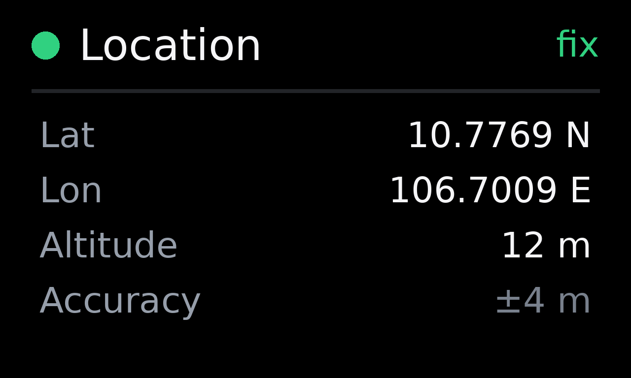
Open Location page: Short press from the Home / Connected screen.
How to access this screen
From the Home / Connected screen, use a short press to open the Location screen.
To return to Home / Connected, use a short press again from the Location screen.
What this screen shows
The Location screen shows GPS-related information in one fixed layout. The displayed values and the top-right status word change depending on the GPS state.
| Field | Meaning |
|---|---|
| Lat | Latitude of the current position |
| Lon | Longitude of the current position |
| Altitude | Height above sea level |
| Accuracy | Estimated position accuracy in meters |
GPS States
| State | Dot | Status Word | Meaning |
|---|---|---|---|
| Searching | Amber | searching | GPS is acquiring a fix |
| Fix | Green | fix | Position has been acquired |
| Off | Grey | off | GPS is not enabled or unavailable |
Action on this screen
| Action | Result |
|---|---|
| Short press | Switch back to Home / Connected |
| Long press | Open Diagnostics |
GPS acquisition may take several minutes. GPS and cellular may share antenna resources, so GPS activity can briefly affect cellular activity. This is normal.
Diagnostics
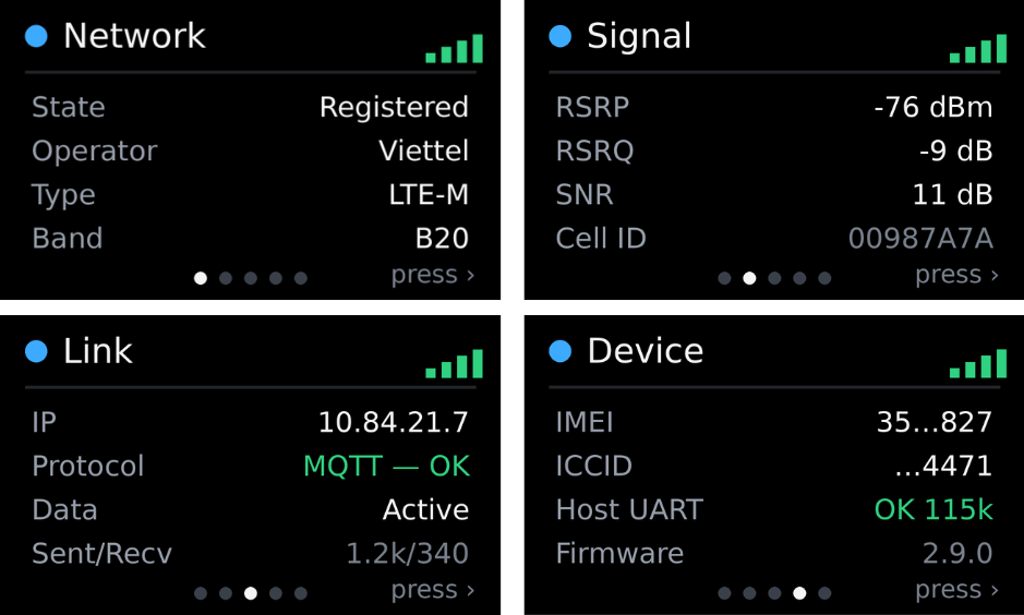
Open Diagnostics page: Long press from the Home / Connected or Location screen.
How to access Diagnostics
From either Home / Connected or Location, use a long press to open Diagnostics.
Diagnostics provide read-only technical values for installers and support. Opening Diagnostics does not change any module settings.
Diagnostics Navigation
| To Reach | Action |
|---|---|
| Open Diagnostics | Long press from Home / Connected or Location |
| Next Diagnostics page | Short press while in Diagnostics |
| Exit Diagnostics | Long press while in Diagnostics |
| Automatic exit | No input for about 30 seconds |
Action in Diagnostics
| Current Diagnostics Page | Short Press | Long Press |
|---|---|---|
| Network | Move to Signal page | Exit Diagnostics |
| Signal | Move to Link page | Exit Diagnostics |
| Link | Move to Device page | Exit Diagnostics |
| Device | Move to GPS page | Exit Diagnostics |
| GPS | Return to Network page | Exit Diagnostics |
Diagnostics Pages
| Diagnostics Page | Information Shown |
|---|---|
| Network | Registration state, operator, cellular type, band |
| Signal | RSRP, RSRQ, SNR, Cell ID |
| Link | IP, protocol, data state, sent/received data |
| Device | IMEI, ICCID, host UART, firmware version |
| GPS | Full-precision latitude/longitude, altitude, accuracy, speed |
Use Diagnostics when you need to collect technical information for installation, field support, or troubleshooting.
Interface Configuration
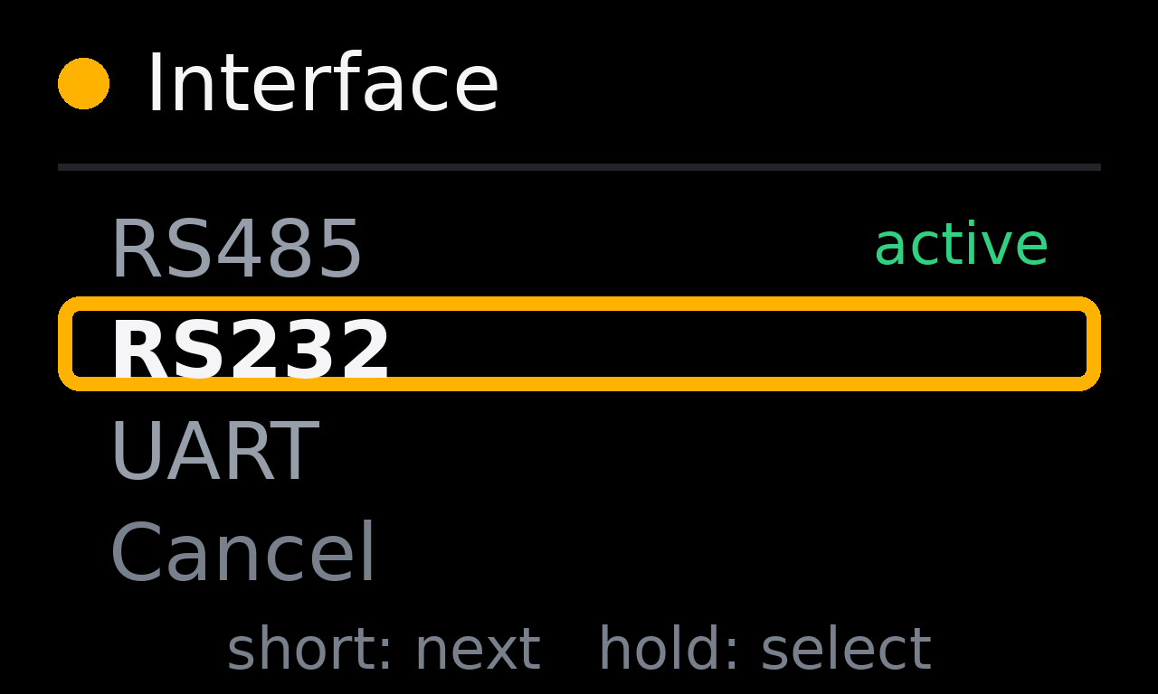
Open Interface Configuration: Hold the button while powering on the module.
How to access Interface Configuration
Interface Configuration is not opened from the normal Home or Location screen.
To enter this mode:
- Power off the module.
- Hold the setting button.
- Power on the module while holding the button.
- Release the button when the Interface Configuration screen appears.
This mode is used to select the host communication interface.
Available Options
| Option | Meaning |
|---|---|
| RS485 | Use RS485 host interface |
| RS232 | Use RS232 host interface |
| UART | Use UART host interface |
| Cancel | Exit without changing anything |
After selecting a new interface, the module displays a confirmation screen and restarts.
After changing the module interface, configure the host equipment to use the same interface. If the host and module interfaces do not match, communication will not work.
Troubleshooting
| Screen / Symptom | How It Appears | Meaning | Recommended Action |
|---|---|---|---|
| No Signal | Appears automatically when no mobile coverage is available | No mobile coverage | Move to a better reception area and check the antenna |
| Check SIM | Appears automatically when the SIM cannot be detected | SIM card is not detected | Power off, reseat SIM, then power on again |
| Service Error | Appears automatically when service is refused or fails | Service refused or unrecoverable network issue | Check SIM plan/service and collect Diagnostics information |
| GPS stays searching | Seen on the Location screen | GPS has not acquired a fix | Wait longer and improve antenna/sky visibility |
| Cannot communicate with host | Seen after changing or mismatching host interface | Interface mismatch | Re-enter Interface Configuration and select the correct RS485/RS232/UART setting for the host |
| Accidentally entered Diagnostics | Happens after a long press from Home or Location | Long press was triggered | Long press again to exit, or wait for automatic exit |