
KSP-N51U-M.2 Quick Start
The KSP-N51U-M.2 is a slot-type internal LTE-M / NB-IoT module in the KORLINX industrial LTE-M product series. This guide helps you install the module into an M.2 2230 Key E socket, connect the U.FL antenna, prepare the host interface, power the module correctly, and verify basic AT command communication.
Unlike the KSE-91A external modem, KSP-N51U-M.2 is an internal slot-in module. This Quick Start focuses on M.2 installation, antenna connection, host interface preparation, USIM preparation, and basic communication verification.
Quick Start Flow
Use the following flow for first-time bring-up.
| Step | Action | Expected Result |
|---|---|---|
| 1 | Review the hardware overview and M.2 pin list | You can identify the M.2 connection, U.FL antenna connector, power pins, GND pins, and UART pins |
| 2 | Power off the host board | The module can be installed safely |
| 3 | Insert and secure the M.2 module | Module is seated correctly in the M.2 2230 Key E socket |
| 4 | Connect the LTE antenna | Antenna is securely connected to the U.FL connector |
| 5 | Prepare the Nano USIM | SIM is ready for cellular network access |
| 6 | Power on the host board | Module receives stable 3.3 V power |
| 7 | Open the host UART port | Serial terminal or host firmware is ready |
| 8 | Send AT | Module returns OK if communication is working |
| 9 | Continue network and GNSS checks | Module is ready for LTE-M / NB-IoT testing |
For the first bring-up, verify the UART path first. A simple AT → OK response confirms that the module is powered and the host UART path is working.
Hardware Overview
The KSP-N51U-M.2 hardware provides a compact M.2 slot-type LTE-M / NB-IoT module form factor with U.FL antenna connection and M.2 2230 Key E pluggable host connection.
Module Overview
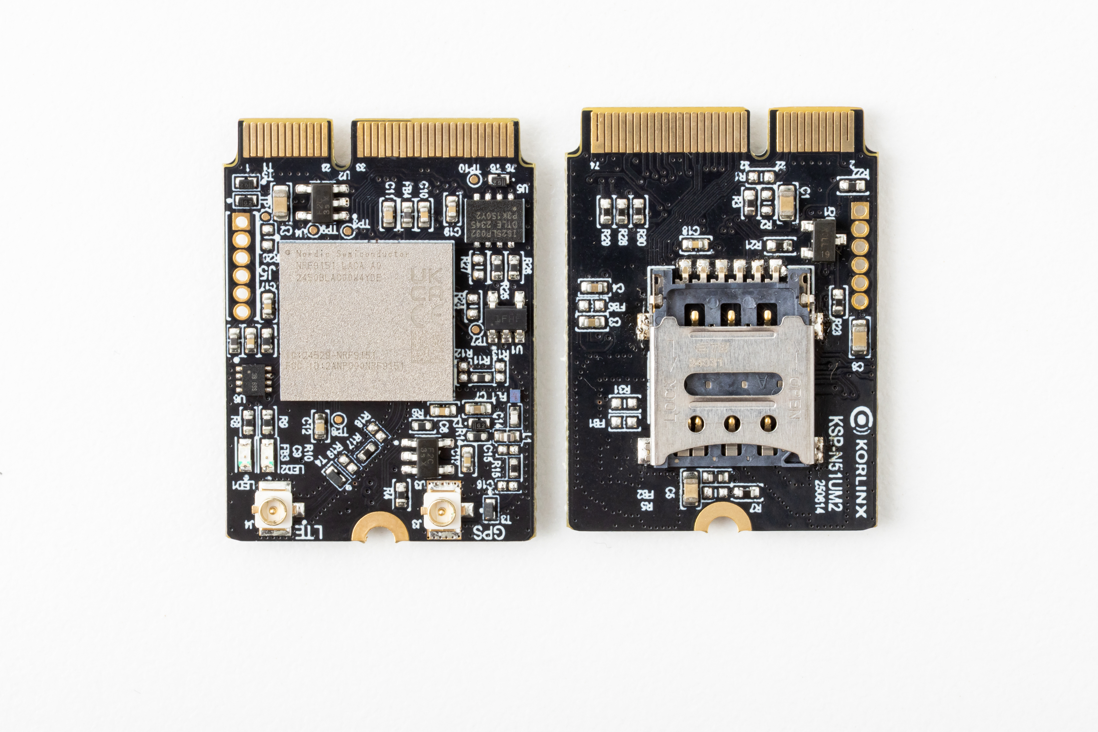
| Part | Description |
|---|---|
| Module type | Internal LTE-M / NB-IoT slot-type module |
| Host connection | M.2 2230 Key E pluggable |
| Antenna connector | U.FL |
| Control interface | AT-COMMAND over UART |
Antenna Connector
The module uses a U.FL antenna connector. Connect the LTE antenna before starting cellular network tests.
Use proper U.FL handling tools or careful hand pressure when connecting the antenna cable. Avoid twisting or lifting the connector at an angle.
M.2 Connector
KSP-N51U-M.2 uses an M.2 2230 Key E pluggable connection. It is intended for host boards that provide a compatible M.2 socket and stable 3.3 V power.
| Item | Description |
|---|---|
| M.2 form factor | 2230 |
| Key type | Key E |
| Host connection | Pluggable M.2 slot |
| Power input | 3.3 V DC from the host board |
Do not insert or remove the module while the host board is powered. Power off the host board before installing, removing, or reseating the M.2 module.
Specification
General
| Item | Specification |
|---|---|
| Model name | KSP-N51U-M.2 |
| Product type | Internal type LTE-M / NB-IoT slot-type module |
| Cellular network | LTE-M / NB-IoT |
| MCU | 64 MHz Arm Cortex-M33 |
| Memory | 1 MB flash + 256 KB RAM, EXT 4 MB flash |
| Modem | Multimode LTE-M / NB-IoT modem |
| Data rate | Up to 375 kbps (LTE-M Cat-M1) |
| Tx power | Up to +23 dBm (LTE-M mode) |
| Frequency | 700–2200 MHz LTE band support |
| Protocol | MQTT, CoAP, HTTP, LwM2M |
| Control | AT-COMMAND (UART) |
| SDK | ESP32, STM32 Series, nRF52 Series |
| GNSS | Supported |
| USIM | Nano USIM, Supported Global and KT |
| Security | Arm TrustZone + Arm CryptoCell 310 |
| Interface | UART, I2C |
| Input voltage | 3.3 V DC |
| Antenna | U.FL |
| Connection | M.2 2230 Key E Pluggable |
| Size | 22 × 30 × 1.0 mm (PCB only) |
Current Consumption
| Mode | Specification |
|---|---|
| Current consumption (Tx) | ~120 mA average in LTE-M mode, varies by band and output level |
| Current consumption (LP) | Under 5 µA in PSM / DRX power-saving mode |
Pin List
The KSP-N51U-M.2 uses the M.2 connector for power, UART, I2C, control, and GPIO-related signals.
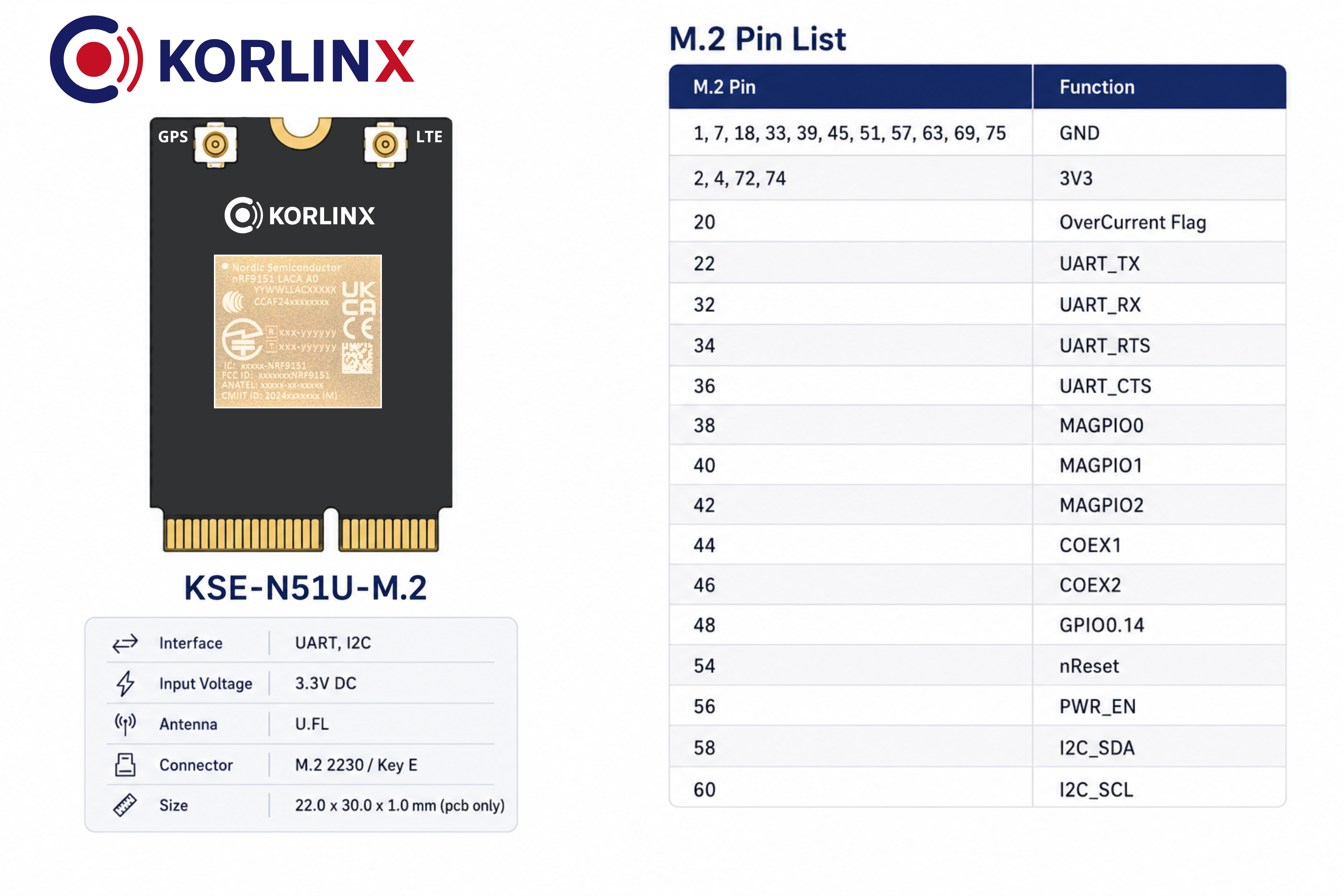
Essential Pins for Quick Start
Use these pins for a basic power and UART communication test.
| Purpose | M.2 Pin | Signal | Connect To / Usage |
|---|---|---|---|
| Power input | 2, 4, 72, 74 | 3V3 | 3.3 V supply from the host board |
| Ground | 1, 7, 18, 33, 39, 45, 51, 57, 63, 69, 75 | GND | Host board ground |
| UART transmit | 22 | UART_TX | Host UART RX |
| UART receive | 32 | UART_RX | Host UART TX |
| Power control | 56 | PWR_EN | Host power enable control, if used |
Confirm the M.2 socket orientation and carrier board schematic before applying power. Incorrect 3.3 V or GND routing may damage the module.
Before You Start
Prepare the following items before installing the module.
| Item | Description |
|---|---|
| KSP-N51U-M.2 module | Main LTE-M / NB-IoT slot-type module |
| Host board | Board with compatible M.2 2230 Key E socket |
| Stable power source | 3.3 V DC supplied by the host board |
| LTE antenna | Antenna connected through U.FL |
| Nano USIM | Active SIM profile for cellular network access |
| Serial terminal | PC tool or host software used to send AT commands |
Before powering on, confirm the M.2 socket compatibility, module seating, antenna connection, Nano USIM preparation, and 3.3 V power design.
Install the Module
1. Power Off the Host Board
Before inserting or removing the module, turn off the host board and disconnect external power.
2. Prepare the Nano USIM
Prepare the Nano USIM according to your host board or product design.
| Check Item | Recommended Action |
|---|---|
| SIM format | Use Nano USIM |
| SIM service | Confirm that the SIM plan supports the target LTE-M / NB-IoT network |
| SIM connection | Verify the SIM circuit or socket in the host design |
3. Connect the Antenna
Connect the LTE antenna to the U.FL antenna connector before running network tests.
| Check Item | Recommended Action |
|---|---|
| Connector type | Use a compatible U.FL antenna cable |
| Connector seating | Press straight down until the connector is seated |
| Cable stress | Avoid pulling or twisting the antenna cable |
4. Insert the M.2 Module
Insert the KSP-N51U-M.2 module into the compatible M.2 2230 Key E socket on the host board.
| Check Item | Recommended Action |
|---|---|
| Socket type | Confirm that the host board uses a compatible M.2 Key E socket |
| Module size | Confirm clearance for the 22 × 30 mm module size |
| Mechanical fixing | Secure the module according to the host board design |
5. Power On the Host Board
After the module is inserted, secured, and the antenna/SIM are prepared, power on the host board.
The module should receive stable 3.3 V DC power from the M.2 socket.
Verify AT Command Communication
After installing the module, connecting the antenna, preparing the USIM, and powering the host board, verify that the UART communication path is working.
Basic Communication Check
Send a basic AT command from your serial terminal or host application:
AT
A normal AT command interface should return an OK response when the host UART communication is working.
If there is no response, check that the host board exposes the module UART interface correctly and that the module receives stable 3.3 V power.
🎉 You're Ready!
Welcome to KORLINX Cellular Module
You've completed the basic hardware connection and UART communication check.
From power wiring to your first AT command response — that's an important first step.
- ✅ Connected the LTE antenna
- ✅ Prepared the Nano USIM
- ✅ Connected power and ground correctly
- ✅ Wired the UART host interface
- ✅ Sent your first
ATcommand - ✅ Received an
OKresponse from the module
What's next?
Network Attach
Continue with LTE-M / NB-IoT network registration and signal checks.
GNSS Preparation
Prepare antenna placement and test location-related features.
Network Attach
Use AT commands to configure the modem and check cellular status.
Host Integration
Integrate the module with your MCU, host board, or application firmware.
Your module is now responding over UART. You can continue with network connection checks and product integration.
Troubleshooting
| Symptom | Possible Cause | Recommended Action |
|---|---|---|
| Module is not detected | M.2 seating, host board, or power issue | Power off, reseat the module, confirm M.2 compatibility, then power on again |
| No AT response | UART routing, power, or serial setting issue | Check host UART routing, serial configuration, and stable 3.3 V power |
| Module does not power on | Incorrect or unstable 3.3 V supply | Confirm stable 3.3 V DC power from the host board |
| Cannot attach to network | SIM, antenna, coverage, or network profile issue | Check Nano USIM, LTE antenna, cellular coverage, and AT command configuration |
| Weak signal | Poor antenna placement or low coverage | Reposition the antenna or test in a better coverage area |
| GNSS does not get a fix | Antenna placement or sky visibility issue | Improve antenna placement and allow more time for first fix |
| Unstable communication | UART routing or host timing issue | Check UART routing, common GND, and host firmware handling |