
Get Started with AS-611Bn
Use this guide with a board whose connector pinout and installed function have been confirmed. Choose the distance or vital-sign procedure for that unit; both functions are not established for every SKU.
Before you begin
- AS-611Bn with a confirmed hardware revision and connector orientation
- A compatible power supply for the fitted power-input option
- A 3.3 V logic USB-to-UART adapter and a serial terminal
- The command line ending specified for the installed firmware
Command termination The supplied v4.0 manual requires lowercase ASCII commands but does not specify CR, LF, CRLF, or another terminator. Obtain the correct setting from the supplier before sending the command examples below. Each line shows command text, not a complete byte-level transaction.
1. Connect power and UART
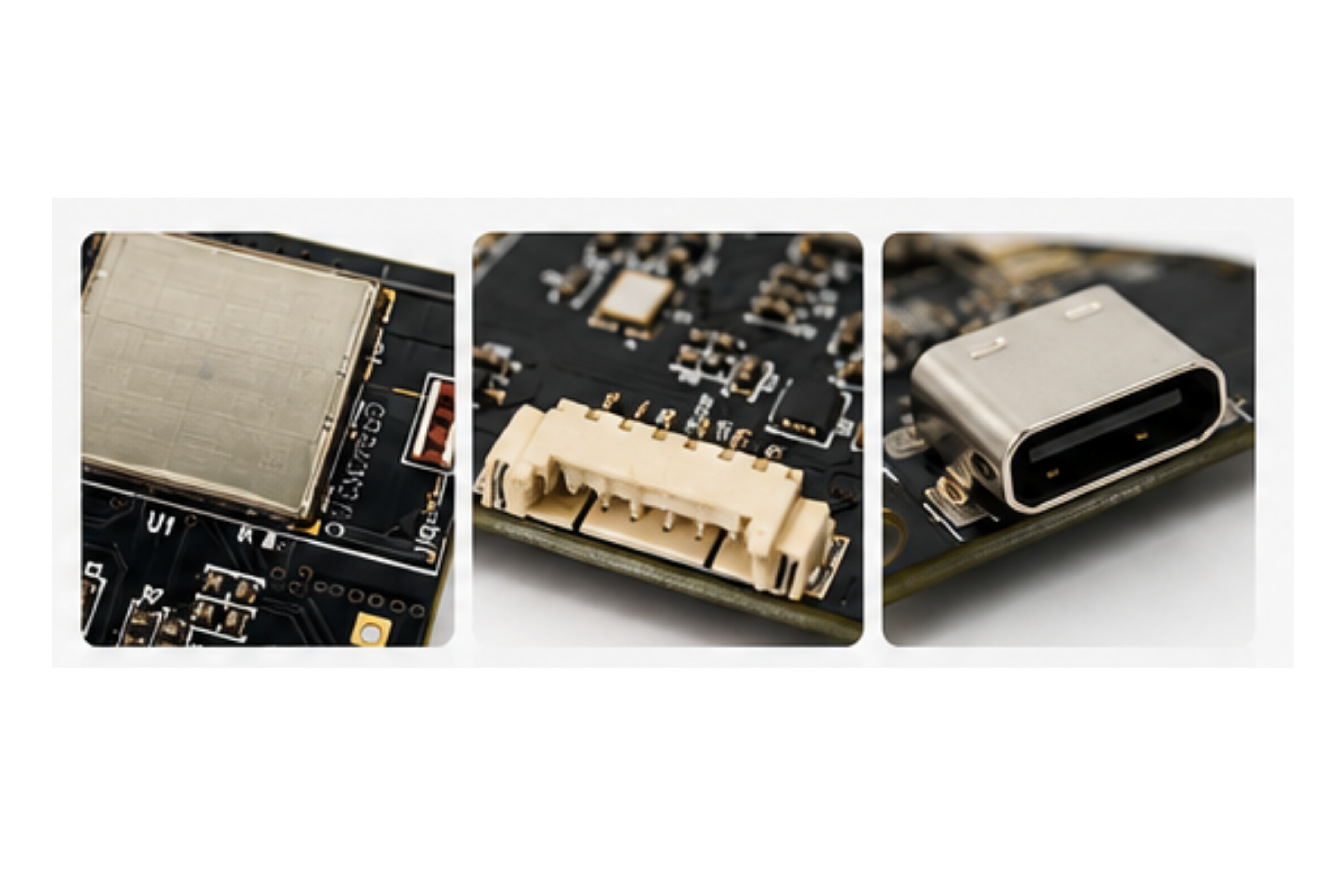
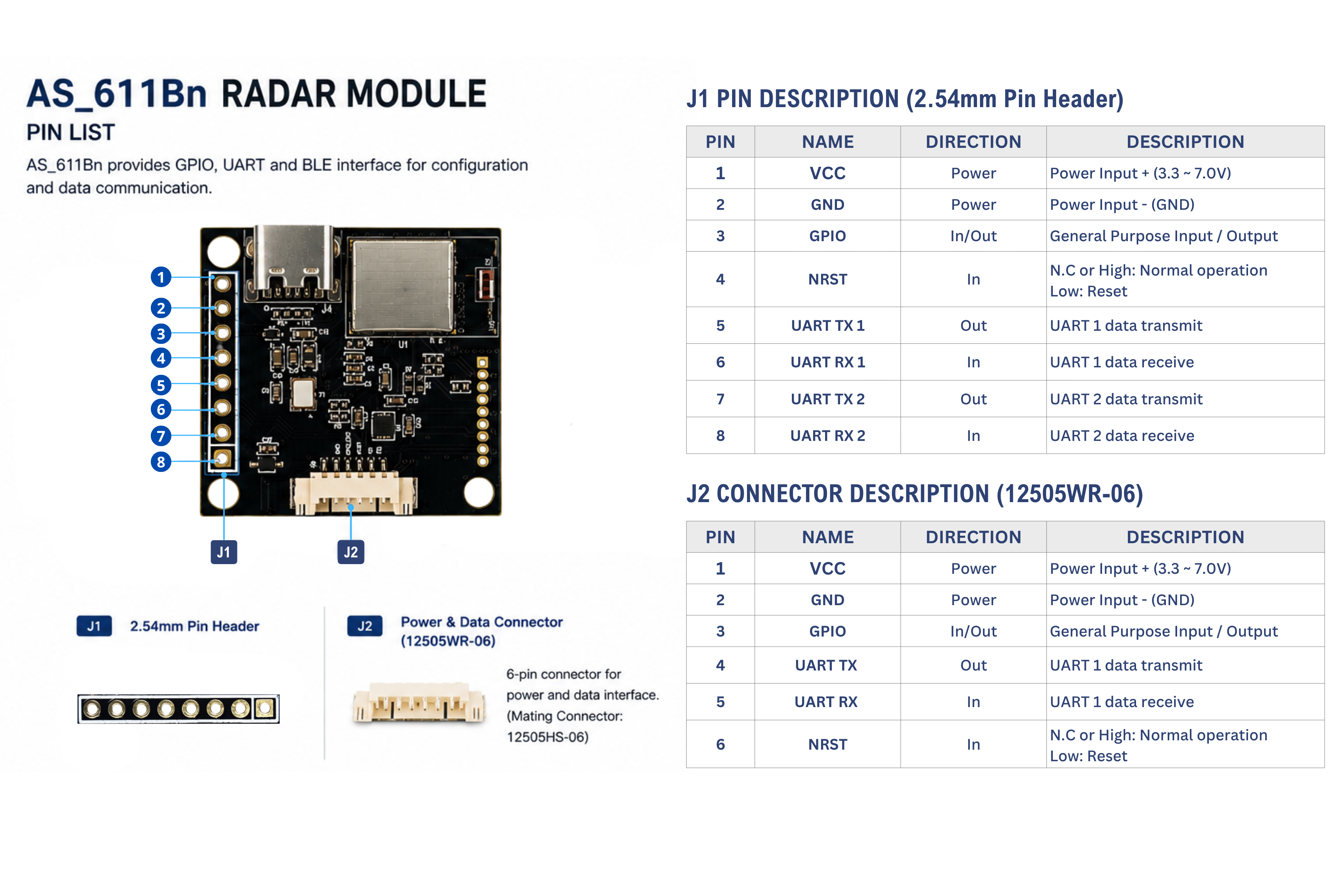
With power disconnected, confirm the actual connector's pin numbering using the hardware overview.
| Module signal | Connection |
|---|---|
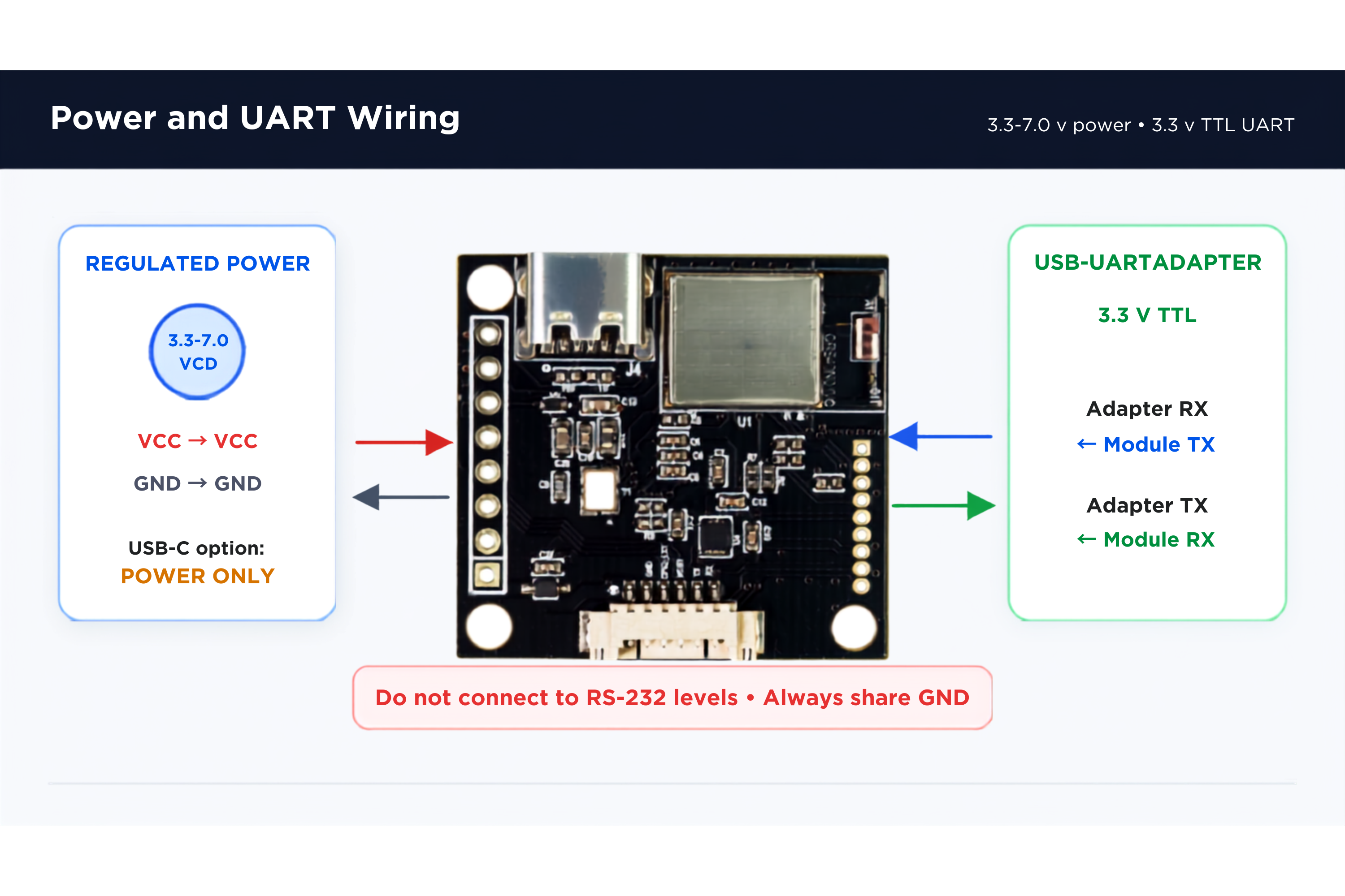
| VCC | Regulated supply appropriate for the confirmed input; manual VCC range is 3.3–7.0 VDC |
| GND | Supply ground and adapter ground |
| UART TX1 | Adapter RX |
| UART RX1 | Adapter TX |
Leave NRST unconnected for normal operation as described in the manual. GPIO and UART2 are not needed for this procedure. If using the fitted USB-C power input, confirm its supply requirements; USB-C is power-only and does not replace the UART data connection.
Electrical levels The adapter's TX/RX logic must be 3.3 V compatible. Do not connect directly to RS-232 or apply the module's supply voltage to signal pins. Use one confirmed power-input path for this setup.
2. Open the terminal and apply power
| Setting | Documented default |
|---|---|
| Baud rate | 460800 bps |
| Data bits | 8 |
| Parity | None |
| Stop bits | 1 |
| Flow control | None |
| Encoding | ASCII |
A previously configured unit may retain a different baud rate. The documented supported values are 115200, 230400, 460800, and 921600 bps.
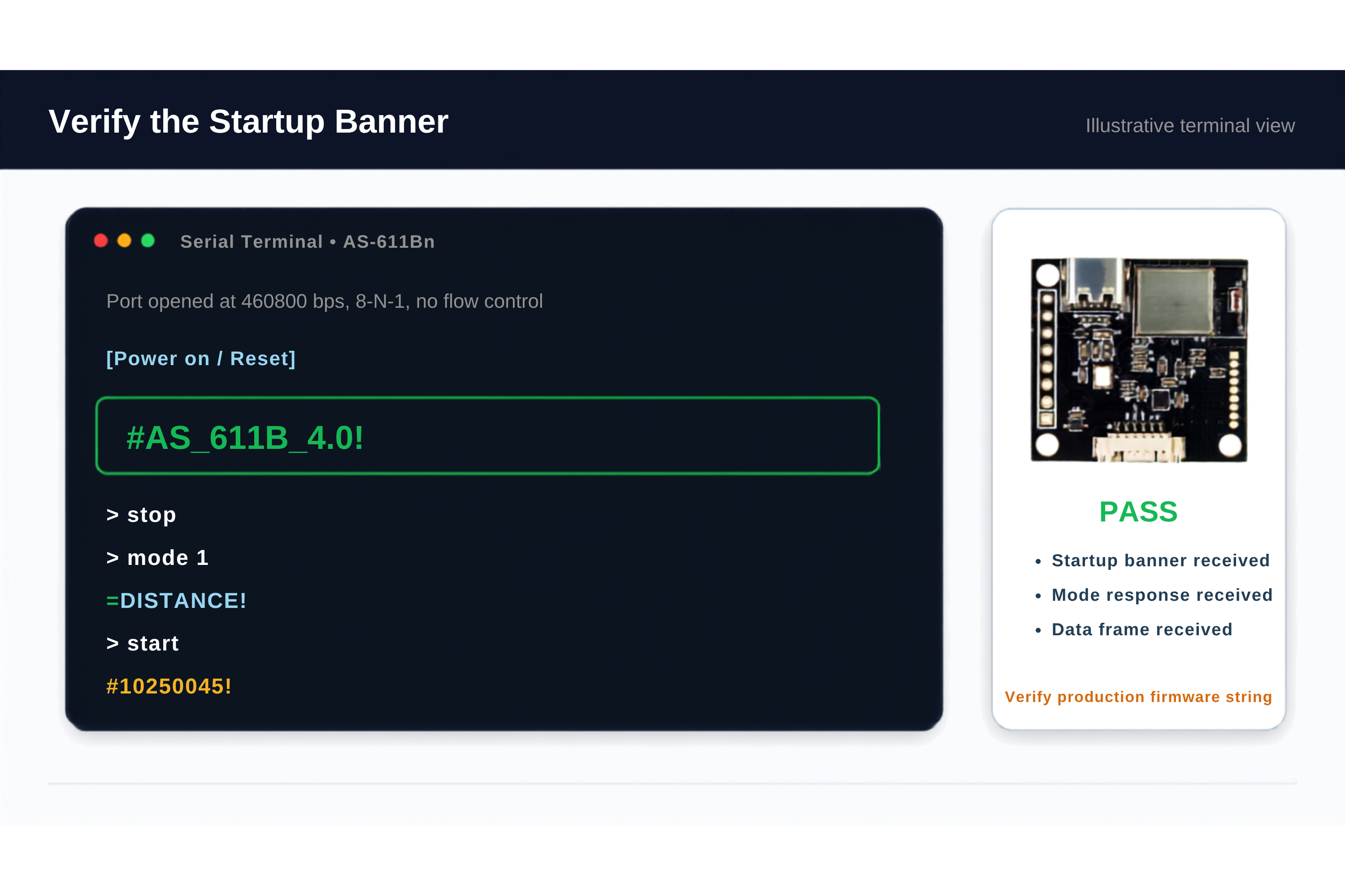
The manual lists this startup string:
#AS_611B_4.0!
Record the actual string and firmware information. The banner is a status message, not a distance frame.
3. Choose the supported sensing function
Distance
For a unit confirmed to support the documented distance commands:
stop
mode 1
The documented mode response is =DISTANCE!. Follow Distance Detection to establish a valid range, then select output timing and start:
outtime 1
start
The manual's illustrative frame #10250045! means object 1 at 250 cm with reflected strength 45. Your measured values will depend on the scene. A documented no-target message is #0!, emitted every 15 seconds while no object is detected.
Vital sign
For a unit confirmed to support the documented vital-sign commands:
stop
mode 2
The documented response is =VITAL!. Follow Vital-Sign Detection to establish the range, then send:
wave 0
exten 0
start
Place one person within the configured zone, with the radar facing the chest. Ask the subject to remain steady for more than 20 seconds; this does not guarantee a result at a fixed time.
The documented simple frame pattern is %ABBBCCDDD!: state, heart rate, breathing rate, and distance in centimeters. State 3 means a vital-sign result is available. Interpret the fields using the protocol reference, including its frame-length discrepancy note.
4. Check the result
- Confirm readable serial data at the unit's configured baud rate.
- Confirm the selected mode response before interpreting measurement frames.
- For distance, compare a measured target distance with the actual setup. A no-target message verifies communication, not ranging accuracy.
- For vital signs, wait for state
3; moving/calculating states are not confirmed measurements. - Retain raw data, settings, board revision, and firmware information when investigating an unexpected result.