
AS-613 60 GHz Radar Module Overview
AS-613 is a compact 60 GHz multi-channel FMCW radar module for indoor position, presence, and closest-person vital-sign sensing. It integrates a 1 TX/3 RX antenna system and signal-processing software on a 32 × 30 mm board and provides GPIO, TTL UART, optional USB-C hardware, and an indicator LED.
Official reference This page follows the AS-613 User Manual, Ver.1.3.1 Jul.2026. Where a command table differs from a product specification or protocol section, this documentation identifies the section used for setup.
Hardware overview
- 60 GHz multi-channel FMCW radar
- Integrated antenna and signal-processing software
- 1 transmit channel and 3 receive channels
- 32.0 × 30.0 mm board outline
- P3 2.54 mm header option
- P1 board-connector option
- J1 USB-C option
- GPIO, TTL UART, USB listed in the manual, and status LED
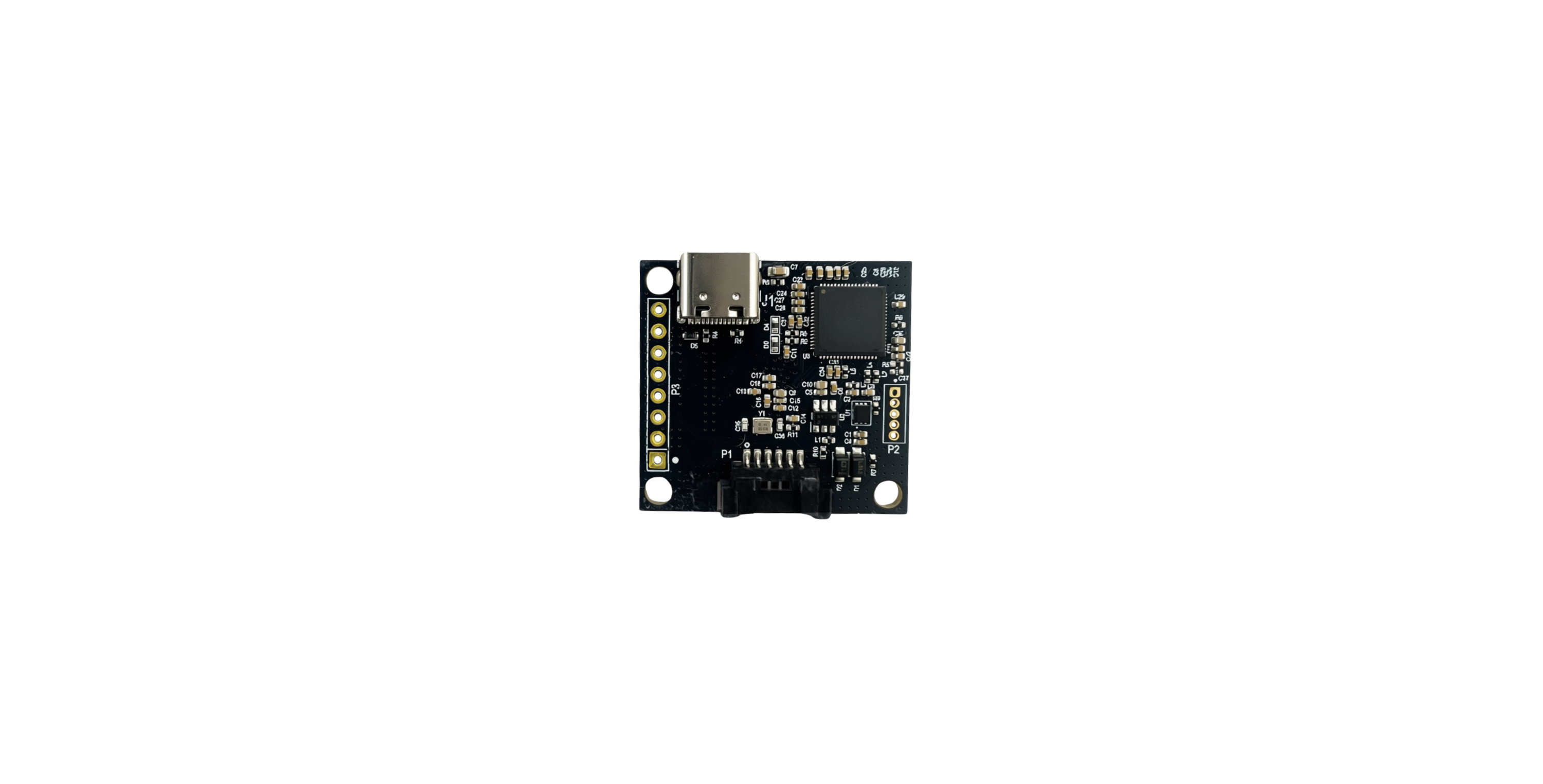
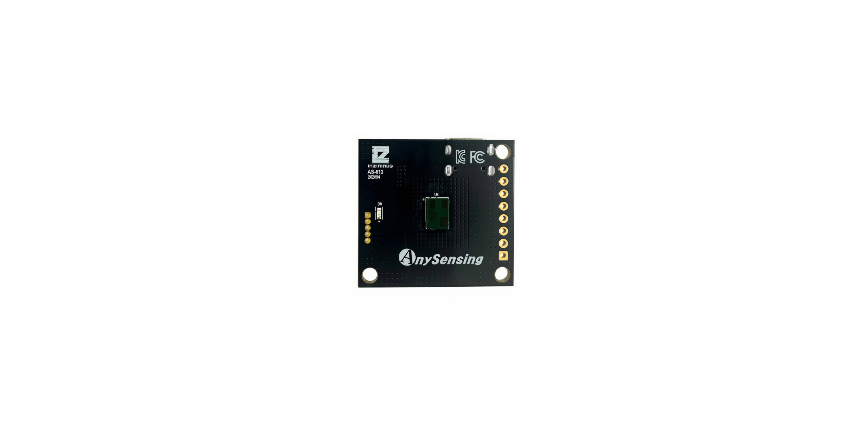
Flat illustrations: component side · antenna side.
The photographs identify the physical board faces. Printed certification marks alone do not establish certification status.
Connector-name difference
The component-side silkscreen shows P3 beside the 2.54 mm header and P1 beside the board connector. The manual v1.3.1 describes P1 as the 2.54 mm header and P3 as the six-pin board connector. The pin map below follows the confirmed production-board reference: P3 is the header, with Pin 1 at the top in the illustrated orientation. The manual also places header Pin 1 at the opposite end; do not mix its orientation with this production pin map.
Specifications
| Item | Value documented in the supplied manual |
|---|---|
| Model | AS_613_AI in the specification table; AS_613 elsewhere |
| Size | 32.0 × 30.0 × 3.35 mm without connector |
| Size with connector | 32.0 × 30.0 × 5.1 mm |
| Weight | 3.15 g |
| Transmit frequency | 60 GHz |
| Antenna | 1 TX, 3 RX |
| TX EIRP | 11 dBm |
| Antenna gain | 3 dBi |
| RF pattern (-3 dB width) | 120° horizontal, 120° vertical |
| Supply voltage | 3.3–5.5 VDC |
| Typical / maximum power | 350 mW typical / 800 mW maximum |
| Operating temperature | -20 to 85 °C |
| Storage temperature | -40 to 150 °C |
| Interfaces | 1 GPIO, 1 TTL UART, USB |
| Distance resolution | 12 cm |
The specification table defines a 3.3–5.5 VDC supply. The feature list and connector table show 3.3–7.0 V. This guide uses the narrower specification-table range for setup.
Pin map
The connector names and orientation below follow the confirmed production pin map. With USB-C at the top, P3 is numbered 1–8 from top to bottom.
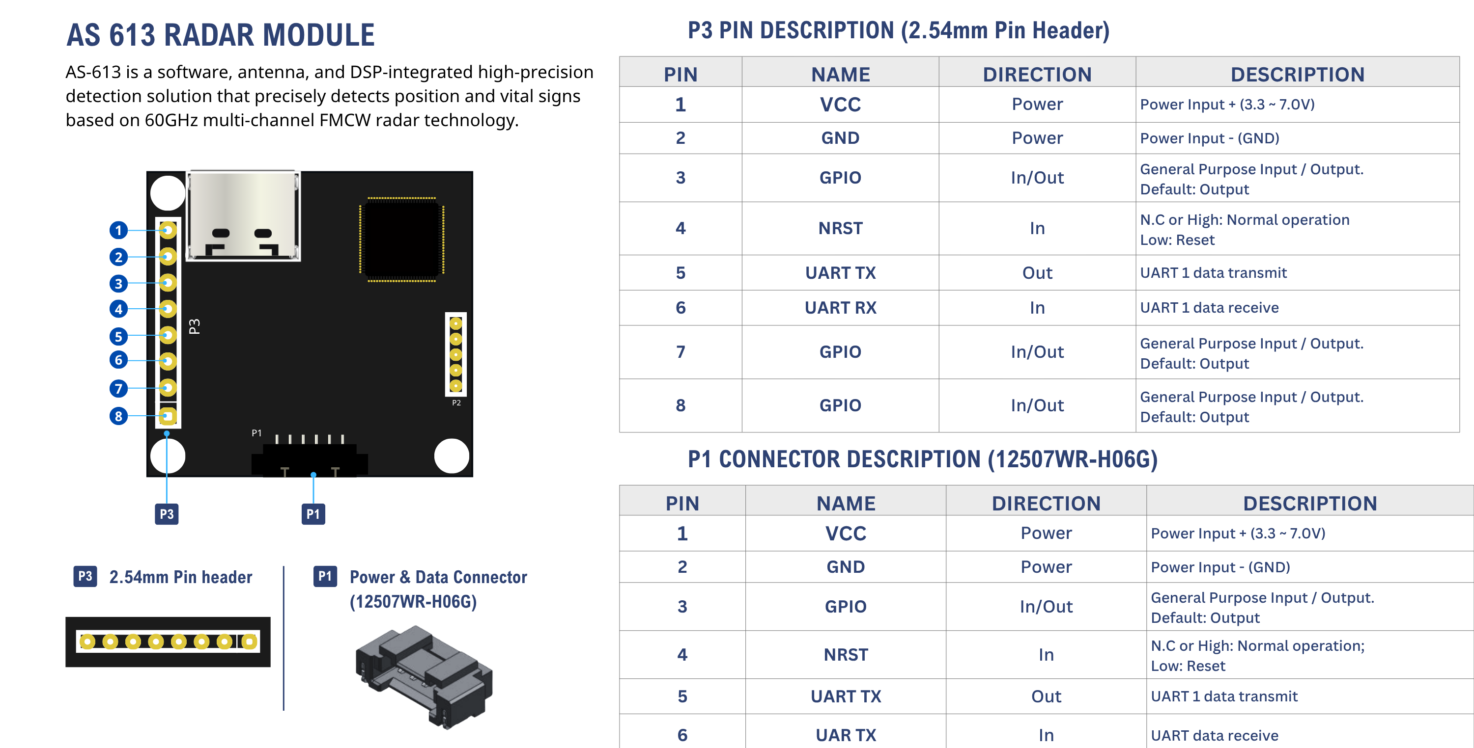
P3 is the eight-pin header; P1 is the six-pin connector. The P1 Pin 6 label in the image has a typo: its input direction and receive description identify UART RX.
| Pin | Signal | P3 header | P1 connector |
|---|---|---|---|
| 1 | VCC | Power input | Power input |
| 2 | GND | Ground | Ground |
| 3 | GPIO | Output by default / configurable input | Output by default / configurable input |
| 4 | NRST | Open or High: normal; Low: reset | Open or High: normal; Low: reset |
| 5 | UART TX | Module transmit | Module transmit |
| 6 | UART RX | Module receive | Module receive |
| 7 | GPIO | Output by default / configurable input | Not used |
| 8 | GPIO | Output by default / configurable input | Not used |
P3: 2.54 mm pin headerP1: six-pin board connector optionJ1: USB-C connector
The manual states that GPIO is an output by default: High when a target is detected and Low when no target is detected. When configured as input, the last character of the output data is described as being used for output, but the exact behavior is not defined clearly enough for implementation.
Electrical details not specified The manual does not define GPIO current limits, pull states, NRST timing, UART absolute maximum ratings, ESD limits, connector current ratings, or USB-C wiring.
The manual names connector options 12507WS-H06G and 12507WR-H06G. These refer to the six-pin connector labeled P1 on the production board. Its connector illustration contains 12507WS-H60G; use the part number from the written pin-description text when selecting the connector.
Sensing modes
| Mode | Installation | Main output | Availability |
|---|---|---|---|
| 1 | Wall/side | Position and reflected energy | Default |
| 2 | Ceiling | Floor-plane position and reflected energy | Default |
| 5 | Wall/side | Closest-person heart rate, breathing rate, waveform, and position | Default |
| 6 | Wall | Position slots plus closest-person vital signs | Default |
| 11 | Wall | Advanced vital signs with RMSSD and SDNN | Additional license |
| 12 | Ceiling | Restroom occupancy/posture-related state and breathing | License status to confirm |
| 13 | Ceiling or wall | Hospital-bed state, vital signs, fall-risk/event, and pressure-ulcer-risk states | Additional license |
| 14 | Wall, ceiling, or corner | Presence tracking; optional closest-person vital output | Additional license |
The manual says evaluation samples include option modes, while mass-production units depend on license status.
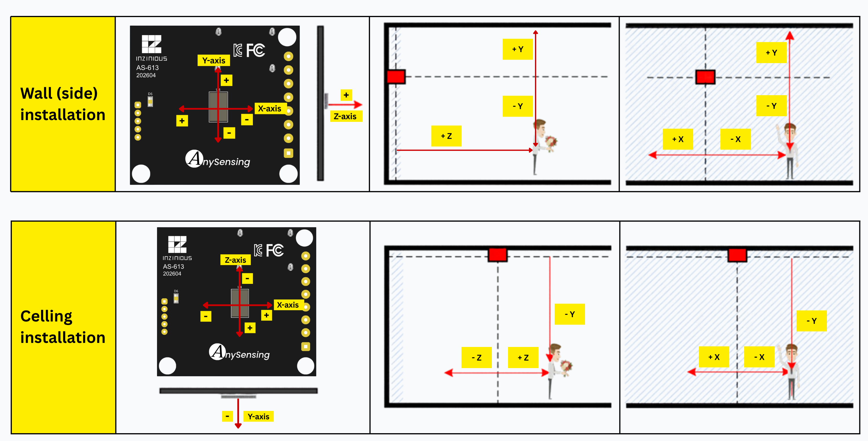
Coordinate system
For wall installation:
- X: left (-), right (+)
- Y: down (-), up (+)
- Z: forward (+)
For ceiling installation:
- X: left (-), right (+)
- Y: height below the radar (-)
- Z: backward (-), forward (+)
The manual states that X-axis performance is relatively better than Y- or Z-axis performance. Coordinates are relative to the radar orientation and can be transformed with rotate; wall-mounted modes can compensate a downward tilt with walltilt where supported.
For distance and angle configuration, see Tune the region of interest.
Detection-area controls
AS-613 exposes distance, angle, sensitivity, and target-maintenance settings. The manual documents a configurable angle range of -75° to +75° and a more stable detection range of approximately -50° to +50°. Angle limits provide an approximate filter and must not be treated as a precise physical beam boundary.
Up to five rectangular exclusion zones can be stored for each active mode/install/work profile. Exclusion zones operate on the XZ plane and are intended to suppress fixed or moving reflectors such as furniture, fans, or air conditioners. Configure the final mode and mounting profile before storing exclusion zones.
Ordering structure
AS_613_P/C/U
| Code | Meaning in the manual |
|---|---|
P | 2.54 mm pin header installed |
C | Board connector installed |
U | USB-C connector installed |
Documented examples: AS_613_U, AS_613_PU, and AS_613_CU.
The order-information section defines the suffixes above. Availability and licensed modes depend on the ordered configuration.
Operating limitations
- Position modes detect motion and reflected energy; they cannot inherently distinguish a person from an animal, fan, curtain, cable, or other moving object.
- Stationary-person detection requires enough micro-motion and becomes harder at longer distances.
- Multiple nearby people may merge into one target; a person directly behind another target may not be detected.
- Metallic or densely furnished environments can create multipath, virtual targets, or missed targets.
- Vital-sign output is associated with the closest detected person and can be disrupted by closer motion or objects between the radar and the subject.
- Hand, arm, phone, keyboard, conversation, or other chest-area motion can reduce vital-sign quality.
- The final detection range must be tested in the actual enclosure and installation environment.
Not a medical or life-safety claim The supplied manual does not provide medical-device certification, clinical validation, or regulatory conformity evidence. Do not use AS-613 output alone for diagnosis, treatment, emergency response, fall protection, or other safety-critical decisions.
Pacemakers and implantable devices The manual warns not to use the device within 20 cm of a pacemaker or other implantable medical device and instructs users to consult the physician or device manufacturer first.