
Configure AS-613 Position Detection
AS-613 provides Mode 1 for wall/side installation and Mode 2 for ceiling installation. Both modes report target position and reflected energy through ASCII packets; extended output adds the third coordinate.
Choose the position mode
| Mode | Installation | Normal coordinates | Extended coordinates | Start character |
|---|---|---|---|---|
| 1 | Wall or side | X, Z | X, Y, Z | # distance; * zone |
| 2 | Ceiling | X, Z | X, Y, Z | $ distance; ~ zone |
The manual identifies * and ~ as zone-output start characters but does not provide the corresponding zone-packet layouts in the supplied revision.
The manual does not define the commands that select zone output or the * and ~ field layouts. This guide therefore documents the distance packets only.
Coordinate orientation
Wall installation
- X: left (-), right (+)
- Y: down (-), up (+)
- Z: forward (+)
Ceiling installation
- X: left (-), right (+)
- Y: height below the radar (-)
- Z: backward (-), forward (+)
Use rotate 0|90|180|270 to align the reported coordinates with the physical board orientation. In supported wall profiles, walltilt 0..45 compensates a downward mounting angle.
Coordinate quality The manual says X-axis detection performance is relatively better than Y- or Z-axis performance. Validate every coordinate axis and sign after installing the final enclosure.
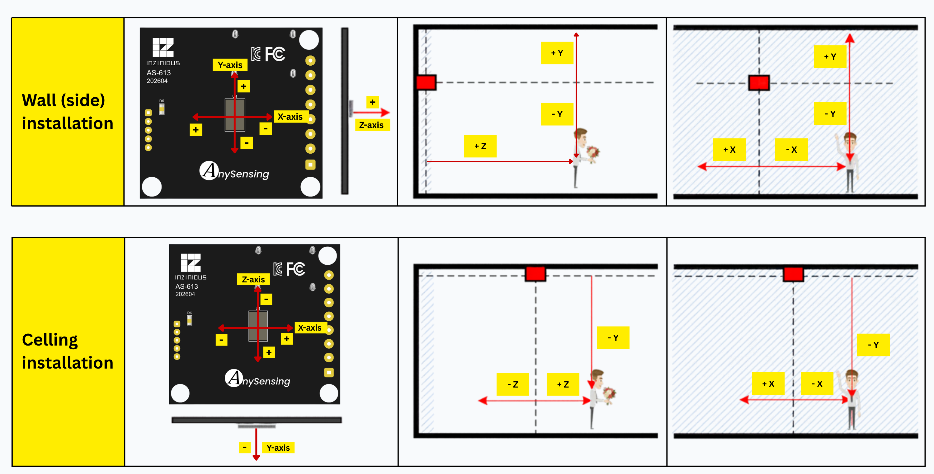
Set rotate and, where supported, walltilt before measuring the final region of interest.
Mode 1: Wall position measurement
The source documents these initial limits:
| Setting | Default |
|---|---|
xmin / xmax | -450 / +450 cm |
ymin / ymax | -200 / +150 cm |
zmin / zmax | +40 / +900 cm |
alrmin / alrmax | -75° / +75° |
adumin / adumax | -70° / +70° |
| Target count | 3 default; 5 maximum |
| Output interval | 100 ms default (10 Hz) |
The manual also lists the product distance specification as 8 m while Mode 1 allows zmax to 900 cm and the feature list says 9 m. Treat 900 cm as a configurable limit, not a validated 9 m human-detection guarantee.
The product specification lists an 8 m distance range. The 9 m value is the Mode 1 configurable Z limit and should be treated as a configuration boundary.
Recommended setup order
Send commands individually, waiting for each response and any restart. These bench sequences include mreset, which clears the active mode settings; record existing settings first.
stop
mode 1
mreset
rotate 0
walltilt 0
info
start
After confirming the default coordinate frame, stop output and narrow the ROI to the actual area. Then adjust angles, sensitivity, entry threshold, and target hold time. Add exclusion zones last.
Mode 1 packet layouts
Normal output:
#ABBBBCCCDDD!
| Field | Length | Meaning |
|---|---|---|
# | 1 | Mode 1 distance packet |
A | 1 | Target index |
BBBB | 4 | Signed X coordinate, cm |
CCC | 3 | Positive Z coordinate, cm |
DDD | 3 | Reflected energy, 0-999 |
! | 1 | End marker |
Extended output (exten 1):
#ABBBBCCCCDDDEEE!
| Field | Length | Meaning |
|---|---|---|
BBBB | 4 | Signed X coordinate, cm |
CCCC | 4 | Signed Y coordinate, cm |
DDD | 3 | Positive Z coordinate, cm |
EEE | 3 | Reflected energy, 0-999 |
Vacancy packet: #0!.
Mode 2: Ceiling position measurement
The source documents these initial limits:
| Setting | Default |
|---|---|
xmin / xmax | -350 / +350 cm |
ymin / ymax | -300 / -40 cm |
zmin / zmax | -350 / +350 cm |
alrmin / alrmax | -75° / +75° |
adumin / adumax | -70° / +70° |
At a 2.5 m ceiling height, the manual describes an approximate 4-5 m floor detection diameter. The actual range depends on ceiling height, body reflection area, motion, clutter, and the installation environment.
Recommended setup order
Send commands individually, waiting for each response and any restart. These bench sequences include mreset, which clears the active mode settings; record existing settings first.
stop
mode 2
mreset
rotate 0
info
start
Set ymin and ymax to represent the required vertical region. Ceiling-mode Y values are negative and positive ymax values are not supported.
Mode 2 packet layouts
Normal output:
$ABBBBCCCCDDD!
| Field | Length | Meaning |
|---|---|---|
$ | 1 | Mode 2 distance packet |
A | 1 | Target index |
BBBB | 4 | Signed X coordinate, cm |
CCCC | 4 | Signed Z coordinate, cm |
DDD | 3 | Reflected energy, 0-999 |
! | 1 | End marker |
Extended output (exten 1):
$ABBBBCCCCDDDDEEE!
| Field | Length | Meaning |
|---|---|---|
BBBB | 4 | Signed X coordinate, cm |
CCCC | 4 | Negative Y coordinate, cm |
DDDD | 4 | Signed Z coordinate, cm |
EEE | 3 | Reflected energy, 0-999 |
Vacancy packet: $0!.
Tune the region of interest
- Measure the physical room and mounting position.
- Set
rotateandwalltiltbefore defining coordinates. - Start with a smaller ROI around the required area.
- Set distance limits with
xmin,xmax,ymin,ymax,zmin, andzmax. - Set approximate angle limits with
alrmin,alrmax,adumin, andadumax. - Validate every boundary with a moving target.
- Tune
sena,senb,senc,senin, andsenoutonly after the geometry is correct.
Distance limits
Use xmin/xmax, ymin/ymax, and zmin/zmax to define the coordinate bounds in centimeters. Apply the axis directions for the selected wall or ceiling installation.
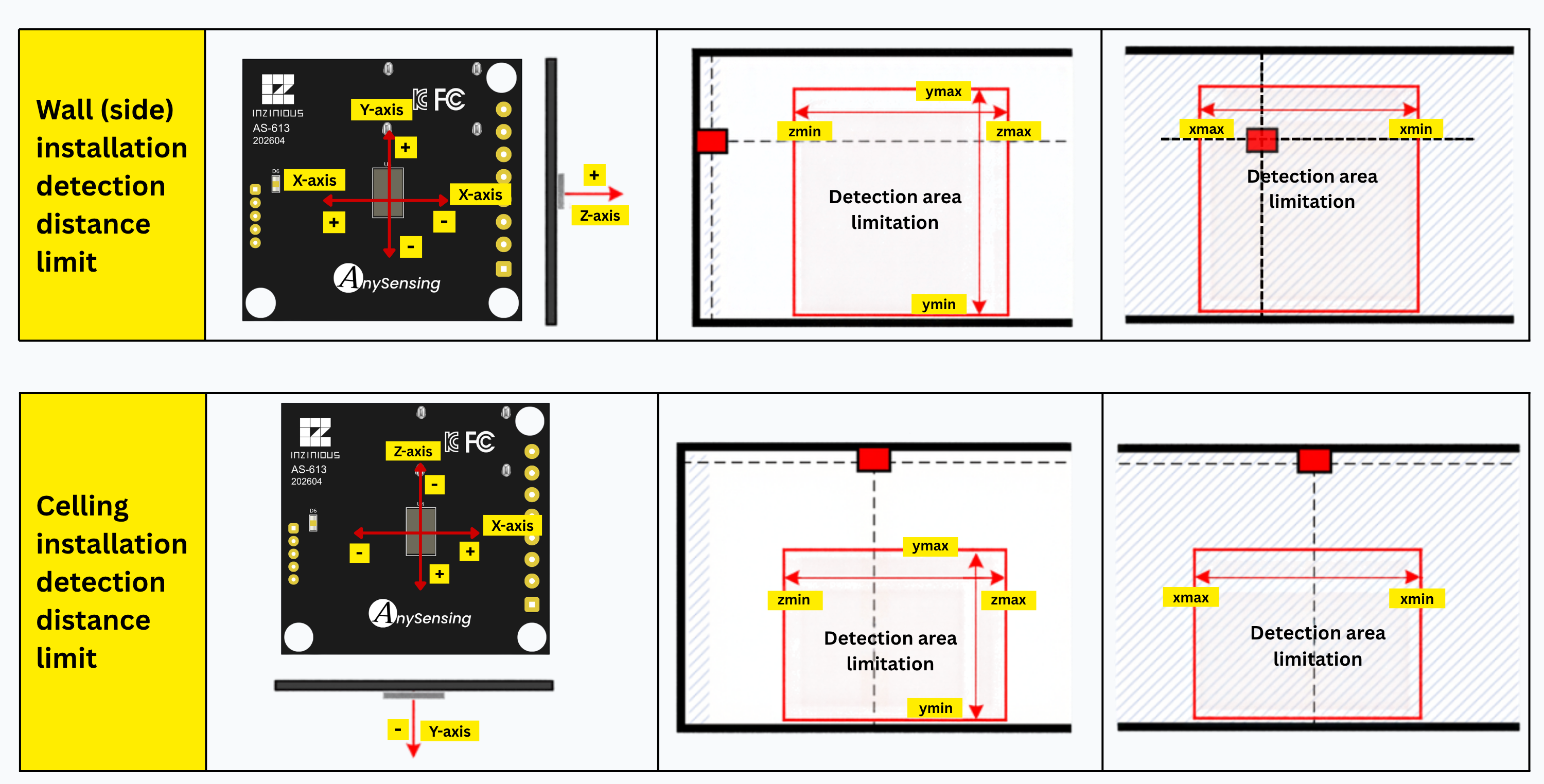
Distance limits define the region along the X, Y, and Z axes for each mounting orientation.
Angle limits
Use alrmin/alrmax for left/right angle limits and adumin/adumax for up/down angle limits in degrees. The diagram shows how these limits relate to each mounting orientation.
The manual warns that angle limits are approximate and less sensitive than distance limits. Validate the boundaries with a moving target after installation.
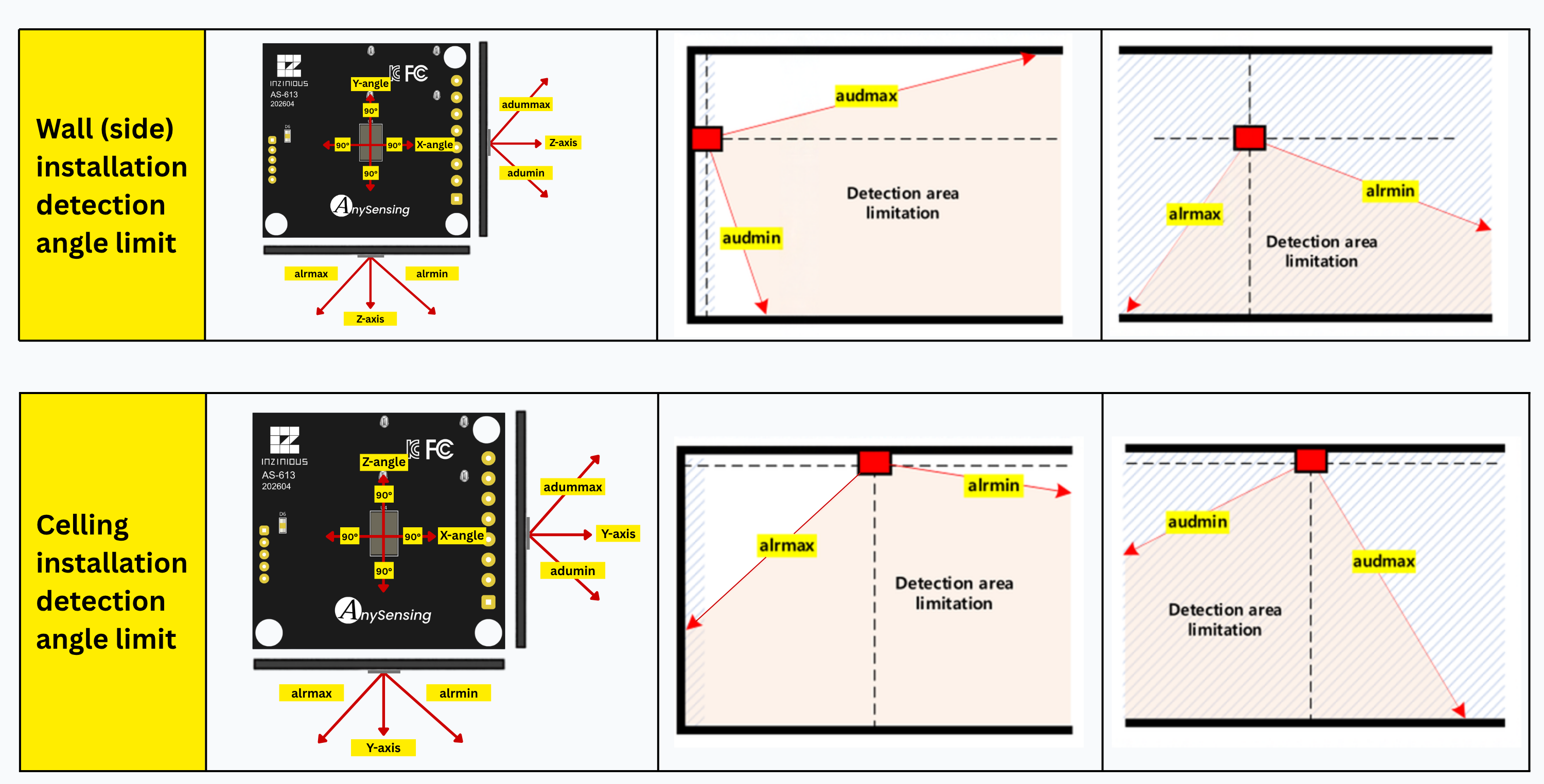
Angle limits use alrmin/alrmax and adumin/adumax; validate their boundaries after installation.
Configure exclusion zones
An exclusion zone is a rectangle on the XZ plane described by center (cx, cz) and half-widths (hx, hz). Up to five zones can be stored per active mode/install/work profile.
Recommended sequence:
- Select the final mode and mounting/work profile.
- Register a zone manually with
exzsetor from a detected target withexzpick. - Inspect stored zones with
exzinfo. - Enable them with
exzon 1. - Validate both false-target rejection and desired-target detection.
Exclusion-zone command forms
The exclusion-zone overview documents exzset <cx> <cz> [hx] [hz] and exzpick <target_num> [hx] [hz]. The command table also presents slot-oriented forms. Query stored zones with exzinfo after each change and avoid scripting slot allocation from an undocumented assumption.
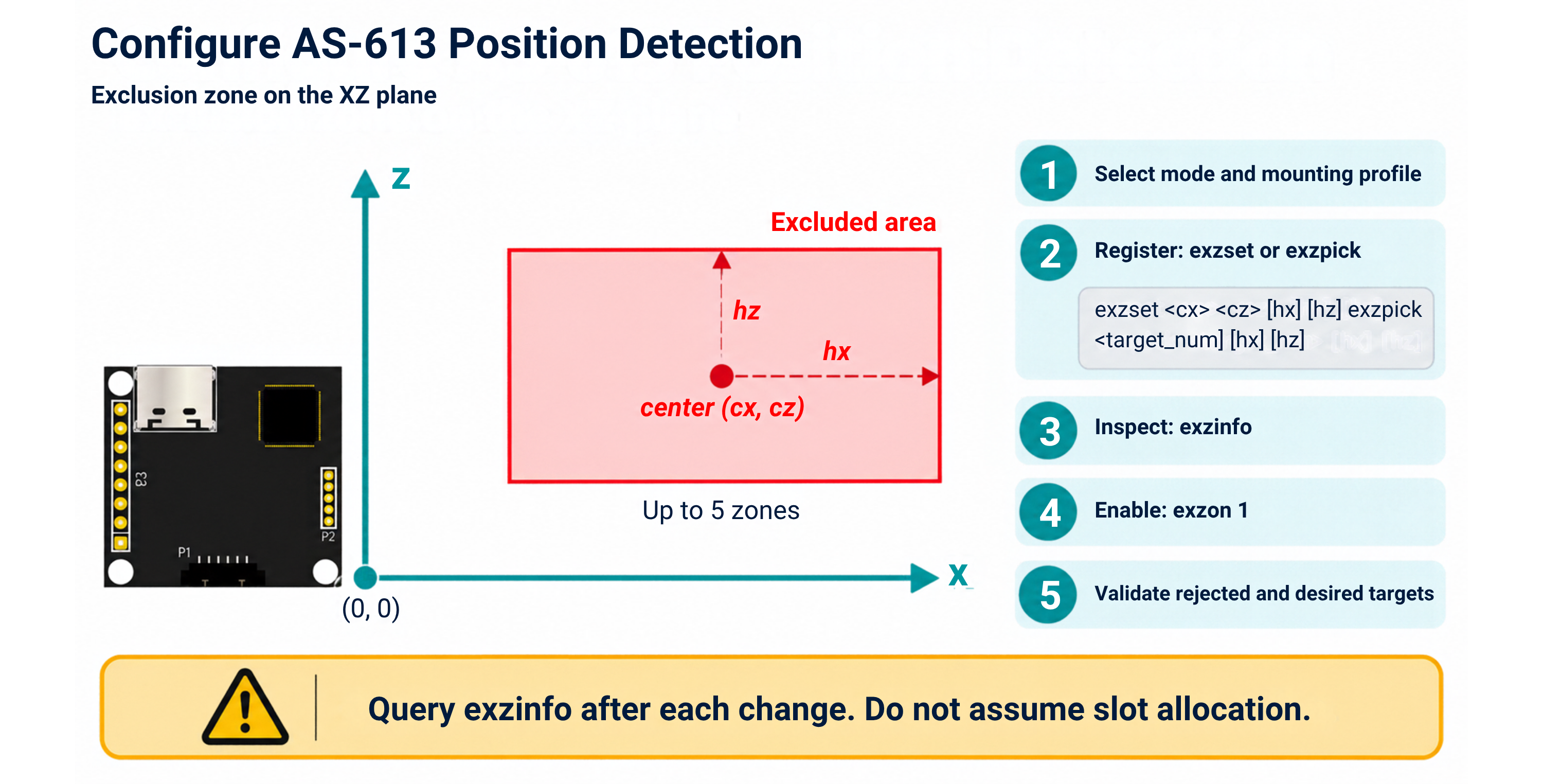
The rectangle uses center coordinates cx/cz and half-widths hx/hz. Query the stored result with exzinfo.
Detection limitations
- Stationary people may not be detected without sufficient breathing or other micro-motion.
- The manual gives examples rather than guarantees: breathing within about 2 m, conversation within about 5 m, keyboard activity within about 7 m, and larger motion beyond 7 m.
- Reflections from metal, monitors, complex furniture, fans, air conditioners, curtains, cables, or pets can create false targets.
- Measured coordinates may fluctuate by 20-30 cm even when the target appears stationary.
- Targets directly behind another target may be hidden.
- Multiple close people may merge into a single target.
Pass criteria
- Reported axis directions match the physical coordinate diagram.
- One target crosses each ROI boundary at the measured location.
- Two separated targets remain distinct at the intended working distance.
- Required targets remain visible after sensitivity and exclusion-zone tuning.
- Vacancy output follows the configured hold and
waitbehavior. - Test records include hardware, firmware, enclosure, mounting, room geometry, target conditions, and acceptance thresholds.