
Get Started with AS-613
This tutorial connects AS-613 to a host through TTL UART, checks the firmware, selects wall position mode, and verifies the first position packet. It deliberately starts with Mode 1 because the licensed care modes require additional installation and validation steps.
Before you begin
You need:
- One AS-613 module with its ordered connector option
- A regulated 3.3–5.5 VDC supply sized for up to 800 mW
- A 3.3 V TTL UART adapter
- A serial-terminal application that supports high baud rates
- The firmware version and licensed-mode list for the unit under test
- An open indoor test area with a clear line of sight
Use the specification-table supply range The specification table defines 3.3–5.5 VDC and up to 800 mW. The feature and pin-description sections also show 3.3–7.0 V. This guide uses the narrower 3.3–5.5 VDC range. The UART protocol is documented as 3.3 V TTL.
Step 1: Identify the connector and Pin 1
Use the confirmed production pin map below. P3 is the eight-pin 2.54 mm header; P1 is the six-pin board connector. With USB-C at the top, P3 Pin 1 is the top header pad. The required signals are VCC, GND, UART TX, and UART RX. Keep NRST open or high for normal operation.
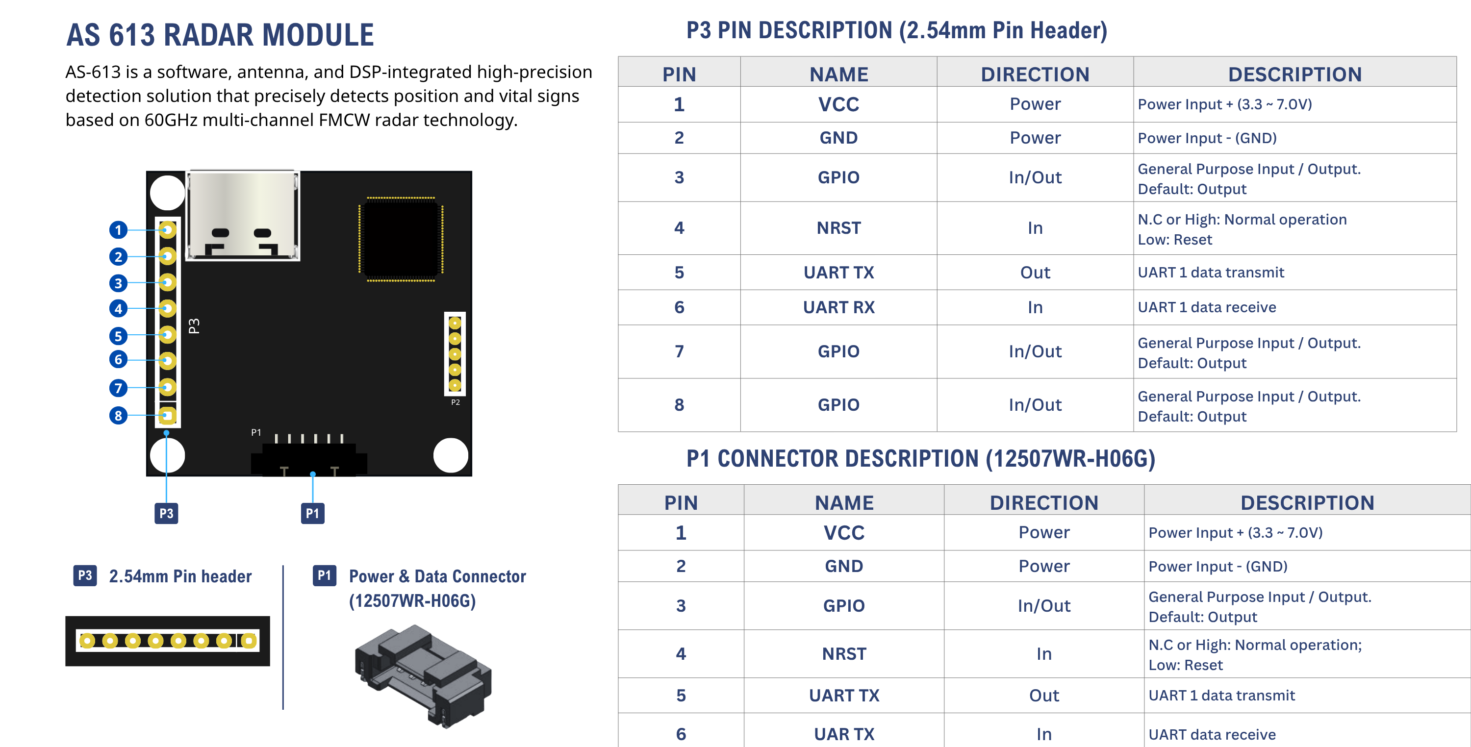
Use the production pin map shown here: manual v1.3.1 reverses the P1/P3 names and the header Pin 1 orientation. P1 Pin 6 is UART RX; its image label contains a typo.
Step 2: Wire power and UART
| AS-613 P3 pin / signal | Host connection |
|---|---|
| 1 — VCC | Regulated 3.3–5.5 VDC supply |
| 2 — GND | Supply ground and UART-adapter ground |
| 5 — UART TX | Host/adapter RX |
| 6 — UART RX | Host/adapter TX |
| 4 — NRST | Leave open or high for normal operation |
Do not connect TTL UART directly to an RS-232 port.
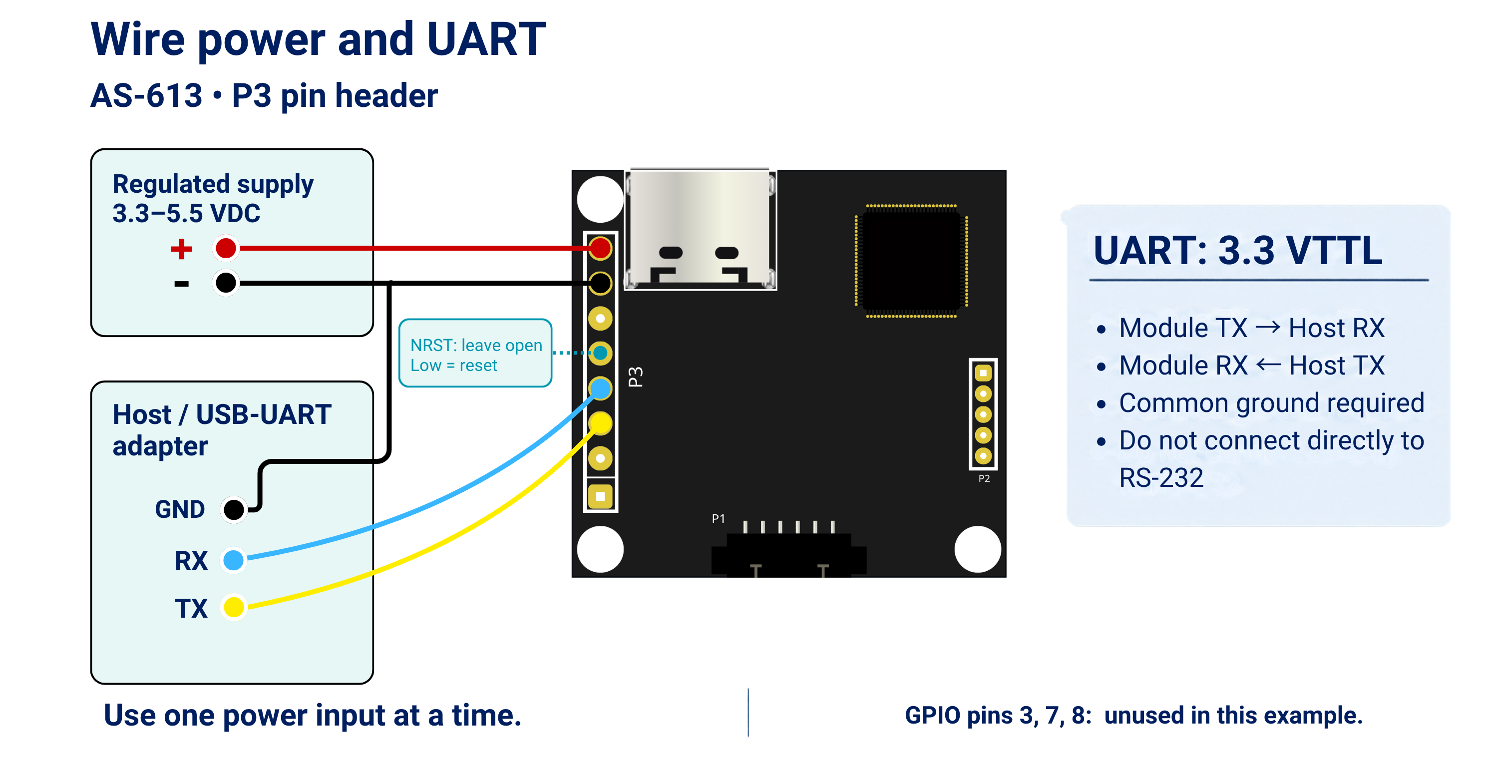
Cross TX and RX, connect a common ground, and leave NRST open or high. Use one power input at a time; USB-C is an alternative power input.
Step 3: Open the serial terminal
The manual agrees on the following format:
Data bits: 8
Parity: None
Stop bits: 1
Flow control: None
Encoding: ASCII
Command case: lowercase
Command terminator: LF or CR
Use 460800 bps, the default defined in the protocol section. The command table shows 921600 as its initial value; if an already-configured unit is unreadable at 460800, check the other supported rates without sending configuration commands.
Step 4: Power the module and identify the firmware
After readable UART communication is established, stop continuous output and query the firmware:
stop
ver
The manual gives this response only as an example:
=61326May12.17.V.1.2!
Do not treat that example as the required production string. Record the real response, hardware revision, supply voltage, baud rate, and licensed modes.
Step 5: Reset Mode 1 and inspect settings
All commands must be lowercase and end with LF or CR. Send each command only after receiving the preceding response.
mode 1
mreset
info
mreset resets only the active mode. The manual recommends freset when previous test settings may cause unexpected behavior, but freset resets all configuration and should be used only in a controlled validation workflow.
Reset behavior Some configuration commands can trigger an automatic reset or fast reset. Allow several hundred milliseconds or more after such a command before sending the next command.
Step 6: Start wall-position output
For an initial open-area test, keep the documented Mode 1 defaults and start output:
start
A normal Mode 1 target packet has this structure:
#ABBBBCCCDDD!
Where:
A: target indexBBBB: signed X coordinate in centimetersCCC: positive Z coordinate in centimetersDDD: reflected-energy value
When no target is detected, the documented vacancy packet is:
#0!
Walk slowly inside the configured region and confirm that target packets change with position. Do not use a hand-wave-only test as proof of human tracking performance.
Pass criteria
- The board powers without supply collapse, abnormal heating, or unexpected current.
- Readable UART data is obtained at 460800 bps or another configured supported rate.
verreturns the module and firmware identity.mode 1,mreset, andinforeturn documented response types.startproduces valid#...!target packets or#0!vacancy packets.- Coordinates respond consistently when one person moves in the test area.
- The status LED turns on when an object is detected, as described by the manual.
Troubleshooting
| Symptom | Check |
|---|---|
| No UART data | Supply range, current capacity, common ground, TX/RX crossing, NRST, connector orientation, and supported baud rate |
| Garbled data | Test only the two documented baud claims, confirm 8-N-1/no flow control, and verify logic levels |
| Command ignored | Use lowercase, terminate with LF or CR, wait for the previous response, and stop output if the terminal cannot separate commands from data |
=OverRange! | Check argument count, numeric format, mode-specific range, and whether the current mount/work profile supports the command |
=UnSupport! | Confirm active mode, mounting profile, work profile, license, and firmware |
| False targets | Move to an open area, narrow the ROI, identify fans/curtains/metal, then add verified exclusion zones only after the final profile is selected |
| Target disappears when stationary | Position mode needs micro-motion; shorten distance and verify with deliberate movement before tuning sensitivity |