
AS-613 UART, GPIO, and USB Integration
AS-613 uses an ASCII command-and-data protocol over UART. The manual also lists USB as an interface and USB-C as a connector/power option, but it does not define USB enumeration, class, endpoint, or data behavior.
UART format
| Item | Documented value |
|---|---|
| Encoding | ASCII |
| Data bits | 8 |
| Parity | None |
| Stop bits | 1 |
| Flow control | None |
| Commands | Lowercase |
| Command ending | LF or CR |
| Default baud rate | 460800 bps (protocol section) |
| Supported baud rates | 115200, 230400, 460800, 921600 bps |
| Response start/end | = / ! |
The command table shows 921600 as the initial baud value. For initial connection, this guide follows the protocol section and starts at 460800. A changed baud rate is retained through freset and mreset.
Electrical level
The manual calls the interface "3.3 V level UART" but also says 1.8 V, 3.3 V, and 5 V signal interfaces are possible. This does not define whether the pins are tolerant, translated, configurable, or dependent on a hardware option.
Use a 3.3 V TTL UART interface The protocol specifies 3.3 V UART. Its statement that 1.8 V, 3.3 V, and 5 V signal interfaces are possible does not describe direct pin tolerance or a level-shifting circuit.
Command transaction model
- Send one lowercase ASCII command terminated with LF or CR.
- Wait for the response ending in
!. - Classify the response.
- If the command triggers reset or fast reset, allow several hundred milliseconds or more before the next command.
- Resume or parse continuous data only after configuration is complete.
The manual recommends several hundred milliseconds or more after reset-triggering commands, but does not define a maximum restart time.
Response types
| Response | Meaning in the manual |
|---|---|
=<value>! | Query or setting completed |
=OverRange! | Argument count, range, or format error |
=UnSupport! | Command not supported in active mode/mount/work profile |
=UnKnown! | Unregistered command or internal queue-registration failure |
=Error! | Internal failure such as flash write failure |
Echo and interleaving
The source does not specify command echo, data/response interleaving, response timeout, retry policy, or atomicity during continuous output. A robust host parser must separate frames by start marker and !, handle partial reads, and treat unknown frames as errors rather than silently discarding them.
Persistent and runtime settings
The manual says configuration stored in nonvolatile memory survives power cycles. Runtime commands including start, stop, pulse, and presenceclr are not retained.
reset: restart while retaining settings.freset: restore all settings to factory state.mreset: restore only the active mode.
The manual says a changed baud rate survives both freset and mreset.
Host parser guidance
AS-613 uses different start characters by mode:
# * $ ~ % @ & ? } { ^ / \ < > =
All documented packets end with !. Read from the serial port as a byte stream, not as fixed terminal lines:
- Buffer until a recognized start marker.
- Continue until
!; apply a host timeout suitable for the application because the manual does not define a maximum response time. - Determine the grammar from the active mode, start marker, extension, and waveform settings.
- Validate exact length and numeric/sign encoding.
- Reject or quarantine malformed frames.
- Timestamp raw bytes before conversion.
Do not assume that every packet from one start marker has the same length: vacancy, short state, normal, extended, and waveform variants differ.
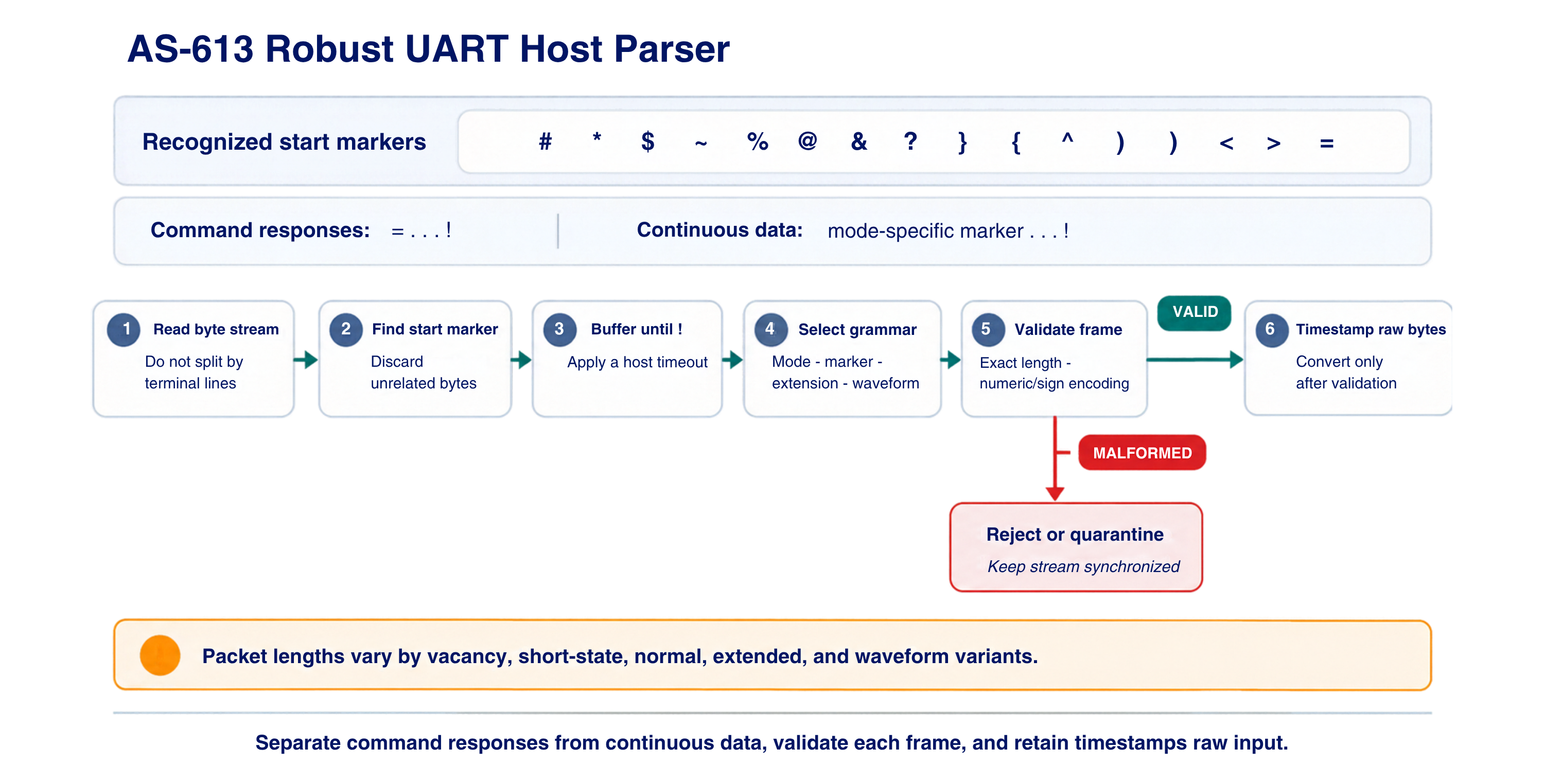
Separate command responses from continuous data, validate each frame, and retain timestamped raw input.
GPIO behavior
The manual says GPIO defaults to output and indicates target detection:
- High: target detected
- Low: no target detected
It also says GPIO can be configured as input and then affects the last character in the data output, but no command, electrical definition, or packet example is provided.
USB-C behavior
The source contains three statements:
- The feature list calls USB-C one of three power-source inputs.
- The specification table lists USB as an interface.
- The pin/ordering sections identify an optional USB-C connector.
No USB class, VID/PID, enumeration, CDC baud behavior, firmware-update behavior, power negotiation, CC resistors, or simultaneous-power rules are provided.
USB behavior described by the manual The manual identifies USB-C as a power input and lists USB as an interface, but it does not document a USB class or host-side data procedure. Use UART for the documented command-and-data interface.

UART is the documented host protocol. The manual does not define a USB host-data procedure or the missing GPIO electrical limits.
Integration pass criteria
- UART uses 3.3 V TTL and starts at the protocol-section default of 460800 bps.
- Every command has a captured success and error response.
- Reset-triggering commands meet a documented timing limit.
- The parser handles partial, concatenated, malformed, vacancy, and response frames.
- Configuration persistence is tested across power cycles and reset types.
- GPIO behavior is measured electrically in every supported mode.
- USB-C use stays within the power behavior described by the manual; UART carries the documented command-and-data protocol.