
AS-614 Licensed Application Modes
AS-614 provides four option modes that require a separate license: raw antenna data, advanced vital signs, restroom monitoring, and hospital-bed monitoring.
Independent safety controls required Do not use AS-614 as the sole fall alarm, patient monitor, emergency-call system, pressure-ulcer prevention control, or life-safety detector. The supplied manual provides no medical-device approval, clinical validation, availability target, fault-detection mechanism, or safety integrity level.
Confirm the license first
Before configuration, record:
- Exact SKU and connector configuration
- Hardware revision
- Firmware returned by
ver - Enabled option-mode list
- License/provisioning method
- Response when an unavailable mode is requested
The AS-614 manual does not define a license-query command or the error response for an unavailable mode.
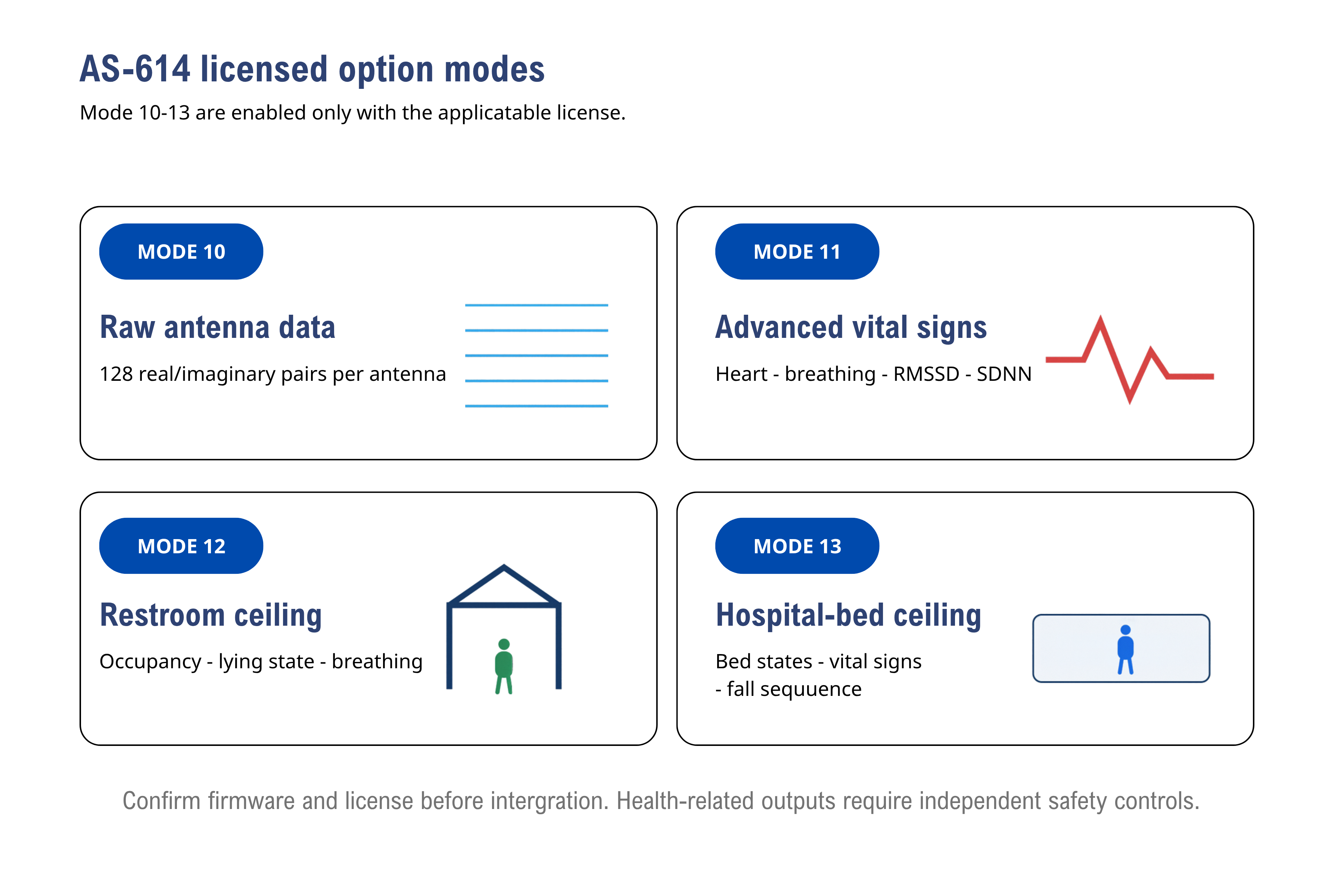
Confirm the license for each option mode. The waveform icon is illustrative; it does not represent an ECG output.
Mode 10: Raw antenna data
Mode 10 outputs signed real/imaginary sample pairs from selected receive antennas. Each selected antenna contributes 128 pairs.
| Command | Output selection | Pair count |
|---|---|---|
raw 1 | Antenna 1 | 128 |
raw 2 | Antenna 2 | 128 |
raw 3 | Antenna 3 | 128 |
raw 4 | Antenna 4 | 128 |
raw 5 | Antennas 1 and 2 | 256 |
raw 6 | Antennas 1 and 4 | 256 |
raw 7 | Antennas 1, 2, and 3 | 384 |
raw 8 | Antennas 1, 2, 3, and 4 | 512 |
The output sequence follows antenna number, with 128 real/imaginary pairs for each selected antenna.
Raw frame delimiter conflict
The Mode 10 example shows a frame enclosed by < and >, while the mode summary says [ and ]. The protocol also says normal packets end in !, which does not match either raw-data form. Do not implement a production Mode 10 parser until the licensed firmware output is captured and the delimiter is confirmed.
Send commands more than 500 ms apart and wait for the module to restart after reset.
Recommended validation:
stop
mode 10
reset
raw 1
reset
start
Capture bytes without line-based assumptions. Verify delimiter, separators, sign encoding, number of pairs, antenna order, update rate, and maximum frame size for every raw setting.
Mode 11: Advanced vital signs
Mode 11 extends Mode 5 with RMSSD and SDNN fields. RMSSD and SDNN begin after more than 30 seconds of stable valid-vital detection; the manual says SDNN stabilizes after at least five minutes.
Use the Vital-Sign Detection guide for setup and packet layouts. HRV field width is two decimal characters, with no documented overflow or unavailable code.
Mode 12: Restroom ceiling mode
Mode 12 detects restroom occupancy and a lying state and can report breathing when the person is sitting or lying. It also reports a warning when a person approaches near the ceiling.
The sensor is ceiling-mounted and faces the person's head. The manual says heart-rate and breathing accuracy are not guaranteed in this geometry and should be used only as reference information.
Documented geometry
| Setting | Default |
|---|---|
| X | -500 to +500 mm |
| Y | -2200 to -200 mm |
| Z | -400 to +1000 mm |
| Left/right angle | 50° to 130° |
| Down/up angle | 50° to 130° |
The manual maps the measured restroom to the generic ROI commands:
- Installation height:
ymin(negative) - Left and right wall distances:
xminandxmax - Back wall distance:
zmin - Front door distance:
zmax - Install the module with the positive Z /
zmaxdirection pointing toward the door
Mode 12 is intended for one person. The manual says it will not function correctly when more than one person is present.
Mode 12 packet
^A!       short form when A is 0, 1, or 4
^ABB!     form containing breathing rate
| State | Manual meaning |
|---|---|
| 0 | Restroom empty |
| 1 | Not defined; the table shows - |
| 2 | Person present in restroom |
| 3 | Person lying down in restroom |
| 4 | Warning: person approaches near the ceiling |
BB is breathing rate per minute. The manual calls ^ABB! a five-byte packet and documents ^0! as the vacancy output.
Undefined state 1
Do not assign a meaning to Mode 12 state 1. Preserve and log it as an undocumented firmware state until R&D provides a definition.
Mode 13: Hospital-bed ceiling mode
Mode 13 is documented for ceiling installation above the chest area of a hospital bed. It reports bed/near-bed state, vital-sign fields, a narrow fall-related sequence, and pressure-ulcer-related warning states.
Installation
- Align the sensor with the bed center in the left-right direction.
- When the bed head faces the wall, install the sensor approximately 75 cm from that wall.
- Default sensor height is represented by the -2200 mm Y limit.
- Set mattress-top height with
hbh(300-700 mm; default 550 mm). - Set mattress width with
hbw(900-1600 mm; default 900 mm). - Set bed-to-wall orientation with
wallside. - Use
hboffset 1..9to compensate a bed movement from 20 cm left to 20 cm right;5is centered.
The detection area includes the bed and extends approximately 30 cm to the sides. The manual illustrations also show 50 cm boundaries around parts of the bed; reproduce these only from an approved engineering drawing.
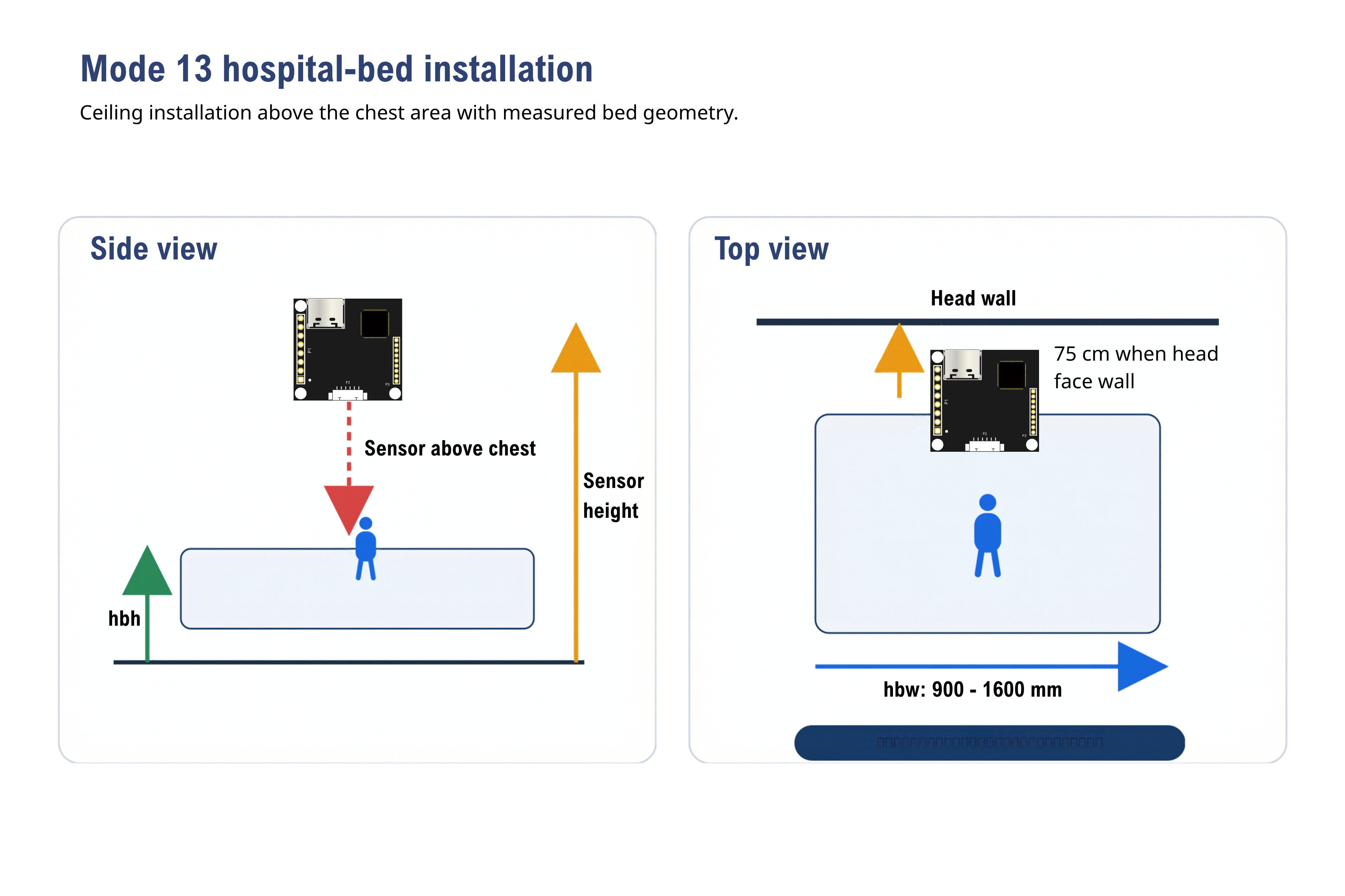
Ceiling installation with the sensor above the chest area. Set hbh and hbw in millimeters; the illustrated wall offset is 75 cm.
Fall-related boundary
The source defines a narrow sequence:
- Patient is lying or sitting in the bed center.
- Patient sits at the bed edge, producing a fall-risk state.
- Patient is then detected sitting or lying on the adjacent floor, producing a fall-occurrence state.
The manual explicitly says falls are not detected in other situations. Do not market Mode 13 as general room-wide fall detection.
Hospital-bed states
| State | Manual meaning |
|---|---|
| 0 | Bed empty |
| 1 | Patient standing beside/outside bed |
| 2 | Patient sitting or lying beside/outside bed |
| 3 | Patient on bed, awake |
| 4 | Patient on bed, tossing/turning |
| 5 | Patient on bed, sleeping |
| 6 | Bed fall-risk warning |
| 7 | Bed fall occurrence detected |
| 8 | Pressure-ulcer-risk warning |
| 9 | High pressure-ulcer-risk warning |
These are firmware output labels, not clinically validated diagnoses.
Mode 13 packets
No waveform:
/A!                       short form for states 0, 1, 2, 7, 8, or 9
/ABBBCCDDEEFFF!           15 bytes
Waveform enabled:
\A!                       short form for states 0, 1, 2, 7, 8, or 9
\ABBBCCDDEEFFFGGG!        18 bytes
The long forms contain state, heart rate, breathing rate, RMSSD, SDNN, and temporary data. The waveform form adds a three-digit respiration waveform before the temporary field.
The manual says heart rate for a patient lying in varied postures should be treated only as reference. In the documented firmware, the vital waveform provides breathing only.
Validation checklist
- Verify license and firmware before installation.
- Confirm measured geometry and coordinate signs.
- Validate every documented state against synchronized observation.
- Test multiple people, occlusion, moving devices, bed movement, power cycling, malformed packets, and stale-state handling.
- Confirm Mode 10 framing before writing a raw parser.
- Treat Mode 12 breathing and all Mode 13 health-related outputs as reference sensor data.
- Add independent emergency and safety controls appropriate to the final product.
- Retain raw logs, setup photos, conditions, sample count, acceptance criteria, reviewer, and date.