
Configure AS-614 Occupancy Detection
AS-614 Mode 3 estimates occupancy from a wall installation, while Mode 4 estimates occupancy from a ceiling installation. Each mode can report one approximate total or a distribution across nine zones.
Not a people counter The manual says the result can differ from the actual number by 1-3 people and explicitly states that the function is not intended for exact people counting or exact person location.
Choose the mode and output
| Mode | Installation | General output | Nine-zone output |
|---|---|---|---|
| 3 | Wall | <A! | >ABCDEFGHI! |
| 4 | Ceiling | <A! | >ABCDEFGHI! |
Use zone 0 for the approximate total and zone 1 for the nine-zone output.
The < and > markers are specific to occupancy modes on AS-614. Do not apply the AS-613 Mode 14 packet meanings to AS-614.
Installation geometry
Mode 3 wall defaults
| Setting | Default |
|---|---|
| X | -4000 to +4000 mm |
| Y | -2000 to +1500 mm |
| Z | +400 to +8000 mm |
| Left/right angle | 0° to 180° |
| Down/up angle | 20° to 160° |
Mode 4 ceiling defaults
| Setting | Default |
|---|---|
| X | -3000 to +3000 mm |
| Y | -3000 to -400 mm |
| Z | -3000 to +3000 mm |
| Left/right angle | 15° to 165° |
| Down/up angle | 15° to 165° |
Measure the final room and narrow these limits to the area that should affect occupancy. The smaller the target and the more cluttered the environment, the narrower the effective angle can become.
Select the duration profile
Use oht to match movement speed:
| Command | Intended environment |
|---|---|
oht 0 | Normal response for meeting rooms or spaces where people remain for longer periods |
oht 1 | Faster response for corridors or short pass-through movement |
Normal response is the documented default.
Recommended setup
For wall occupancy:
stop
mode 3
reset
zone 0
oht 0
reset
info
start
For ceiling occupancy, use mode 4. Send commands individually with more than 500 ms between them.
The manual describes occupancy data as being output approximately every 15 seconds. If an empty area first becomes occupied, the module can immediately output <1! for lighting control and then report the estimated value in the next output.
General occupancy packet
<A!
| Field | Length | Meaning |
|---|---|---|
< | 1 | General occupancy output |
A | 1 | Approximate occupancy value |
! | 1 | End marker |
Vacancy packet: <0!.
The total field is one character, but the manual does not define how values 10–15 are encoded. The packet section says the value can represent up to 15 objects with a default of 10, while the setnum command table lists a range of 1-5 and shows the inconsistent example setnum 10. Do not use setnum to define an occupancy capacity until the active firmware behavior is confirmed.
Nine-zone packet
The detection area is divided into a three-by-three grid:
| Z position | Left (toward Xmin) | Center | Right (toward Xmax) |
|---|---|---|---|
| Toward Zmax | A | B | C |
| Middle | D | E | F |
| Toward Zmin | G | H | I |
Packet:
>ABCDEFGHI!
Each field is one character representing the approximate occupancy in that zone. Vacancy packet: >0!.
Because each zone field is one character, the manual does not explain how values above 9 are represented. Treat non-decimal characters or unexpected frame lengths as unsupported until firmware documentation defines them.
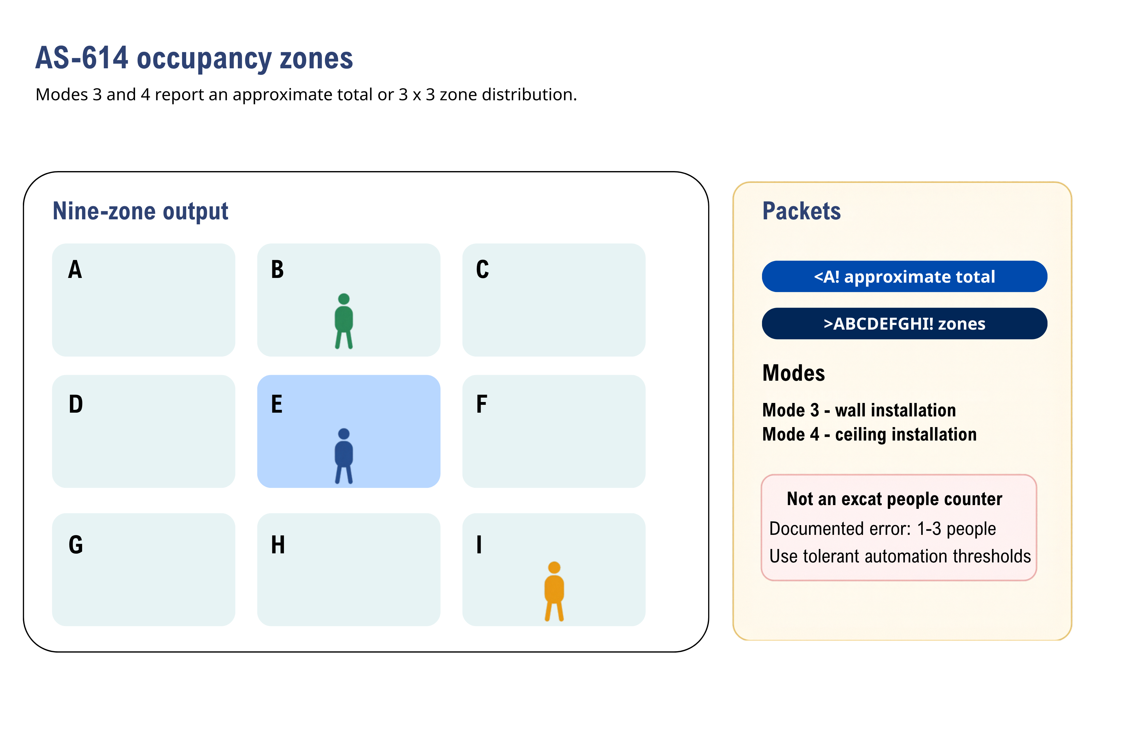
Modes 3 and 4 report approximate occupancy as a total or nine-zone distribution. People shown in the grid are illustrative.
Tune and validate
- Confirm the mounting mode and coordinate frame.
- Limit the ROI to the usable room area.
- Choose
oht 0oroht 1for the expected dwell time. - Start in general output and compare the approximate total with observed occupancy.
- Switch to zone output and walk through A-I individually.
- Repeat with people close together, side by side, partially occluded, stationary, and moving quickly.
- Test fans, moving curtains, pets, doors, carts, and other moving reflectors.
- Define automation thresholds that tolerate documented count error and delayed output.
Pass criteria
- Vacancy and first-entry transitions occur within the application's documented timing budget.
- Mode 3 and Mode 4 use the correct coordinate limits for their mounting orientation.
- Every physical grid cell maps to the intended A-I output field.
- The application remains safe when the estimate differs by 1-3 people.
- Exact billing, access control, evacuation counts, or safety decisions do not depend on this estimate alone.
- Raw UART logs, synchronized observations, room geometry, firmware, and acceptance thresholds are retained.