
Configure AS-614 Position Detection
AS-614 provides Mode 1 for wall/side installation and Mode 2 for ceiling installation. Both modes report position and reflected power through fixed-width ASCII packets. They can also convert X/Z position into coarse one-meter zone codes.
Choose the position mode
| Mode | Installation | Distance output | Zone output | Vacancy |
|---|---|---|---|---|
| 1 | Wall or side | # | * | #0! or *0! |
| 2 | Ceiling | $ | ~ | $0! or ~0! |
Use zone 0 for coordinate output and zone 1 for coarse zone output. Use exten 1 to add Y to coordinate packets.
Coordinate orientation
Wall installation
- X: left (-), right (+)
- Y: down (-), up (+)
- Z: forward (+)
Ceiling installation
- X: left (-), right (+)
- Y: height below the radar (-)
- Z: backward (-), forward (+)
AS-614 uses positive 0-180° angle values rather than signed angles. Left/down is near 0°, and right/up is near 180° according to the manual diagrams.
Mounting orientation
The AS-614 command table does not document rotate or walltilt. Align the board mechanically with the intended coordinate frame and validate all axis signs after mounting.
See the wall and ceiling diagrams in Overview — Coordinate system. Configure coordinate limits in millimeters; position packets report centimeters. Verify physical axis directions after mounting.
Mode 1: Wall position measurement
Documented defaults:
| Setting | Default |
|---|---|
xmin / xmax | -4000 / +4000 mm |
ymin / ymax | -2000 / +1500 mm |
zmin / zmax | +400 / +8000 mm |
alrmin / alrmax | 0° / 180° |
adumin / adumax | 20° / 160° |
| Target count | 3 default; 5 maximum |
The product specification lists an 8 m maximum distance. The manual separately describes an approximately 5 m reliable range for people and says performance depends on angle, motion, target type, and environment. Treat 8 m as an upper product limit, not a guaranteed person-detection range.
Recommended setup order
Send one command at a time and wait more than 500 ms:
stop
mode 1
reset
zone 0
exten 0
reset
info
start
After validating the coordinate frame, stop output, set measured ROI limits, then restart. Use freset only when a full factory reset is intentional.
Mode 1 distance packets
Normal output:
#ABBBBCCCDDD!
| Field | Length | Meaning |
|---|---|---|
# | 1 | Mode 1 coordinate packet |
A | 1 | Target index |
BBBB | 4 | Signed X coordinate, cm |
CCC | 3 | Positive Z coordinate, cm |
DDD | 3 | Reflected power, values above 999 reported as 999 |
! | 1 | End marker |
Extended output (exten 1):
#ABBBBCCCCDDDEEE!
This adds signed Y (CCCC); DDD becomes positive Z and EEE is reflected power. Vacancy packet: #0!.
Mode 1 zone packet
*ABC!
A: target indexB: coarse X zone digitC: coarse forward-Z zone digit
The X/Z plane is divided into approximately one-meter bands. The outermost digits include values beyond the drawn grid. Validate boundary behavior before using the zone code for automation. Vacancy packet: *0!.
Mode 2: Ceiling position measurement
Documented defaults:
| Setting | Default |
|---|---|
xmin / xmax | -3000 / +3000 mm |
ymin / ymax | -3000 / -400 mm |
zmin / zmax | -3000 / +3000 mm |
alrmin / alrmax | 15° / 165° |
adumin / adumax | 15° / 165° |
At a 2.5 m ceiling height, the manual describes an approximate 4-5 m floor detection diameter. Actual coverage depends on height, body reflection area, motion, clutter, and installation geometry.
Recommended setup order
stop
mode 2
reset
zone 0
exten 0
reset
info
start
Ceiling Y values are negative. The command table says ymax is ignored and processed as 0 in one note, while the Mode 2 default table lists ymax = -400 mm. Query info and verify the active firmware before scripting a ceiling-height boundary.
Mode 2 distance packets
Normal output:
$ABBBBCCCCDDD!
| Field | Length | Meaning |
|---|---|---|
$ | 1 | Mode 2 coordinate packet |
A | 1 | Target index |
BBBB | 4 | Signed X coordinate, cm |
CCCC | 4 | Signed Z coordinate, cm |
DDD | 3 | Reflected power, values above 999 reported as 999 |
! | 1 | End marker |
Extended output (exten 1):
$ABBBBCCCCDDDDEEE!
This adds negative Y (CCCC); DDDD is signed Z and EEE is reflected power. Vacancy packet: $0!.
Mode 2 zone packet
~ABC!
A: target indexB: coarse X zone digitC: coarse signed-Z zone digit
The ceiling X/Z plane is divided into approximately one-meter bands. Confirm the center boundary and outer-band behavior with real packets. Vacancy packet: ~0!.
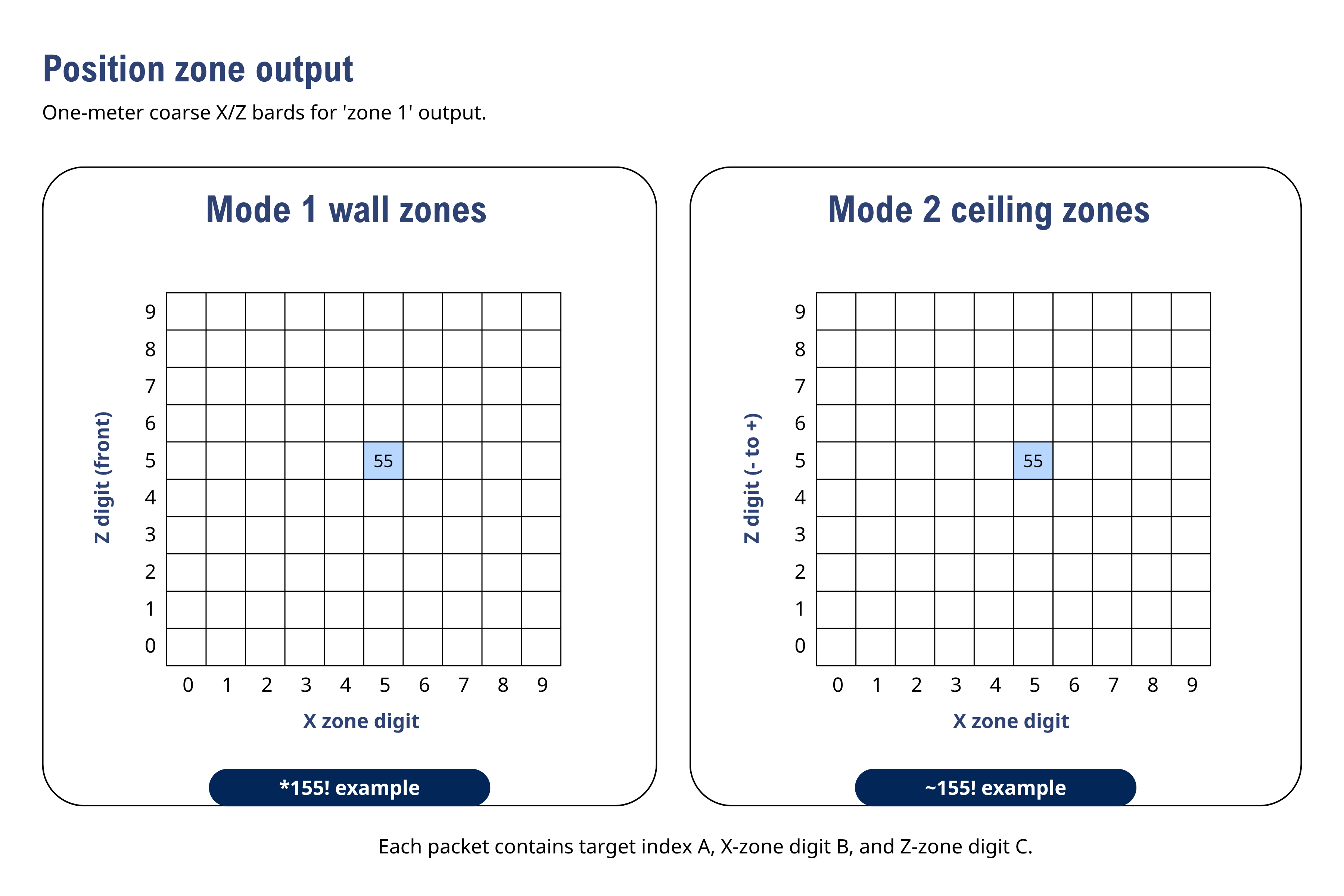
Axes show zone digits, not meters. The highlighted 55 and target-1 packets are illustrative codes, not measured positions.
Tune the region of interest
- Measure the room and mounting position.
- Mount the board in the final orientation.
- Start with an ROI smaller than the physical room.
- Set distance limits in millimeters with
xmin,xmax,ymin,ymax,zmin, andzmax. - Set approximate angle limits with
alrmin,alrmax,adumin, andadumax. - Use
rangeto tune when nearby objects are merged as one target. - Use
responseandptholdonly after geometry is correct. - Validate each boundary with real motion.
Lower pthold values increase sensitivity but also increase noise. The table lists a default of 4 and a setting range that appears as both 3-500 and 4-500. Keep pthold >= 4 unless the installed firmware is explicitly verified for another value.
Distance limits
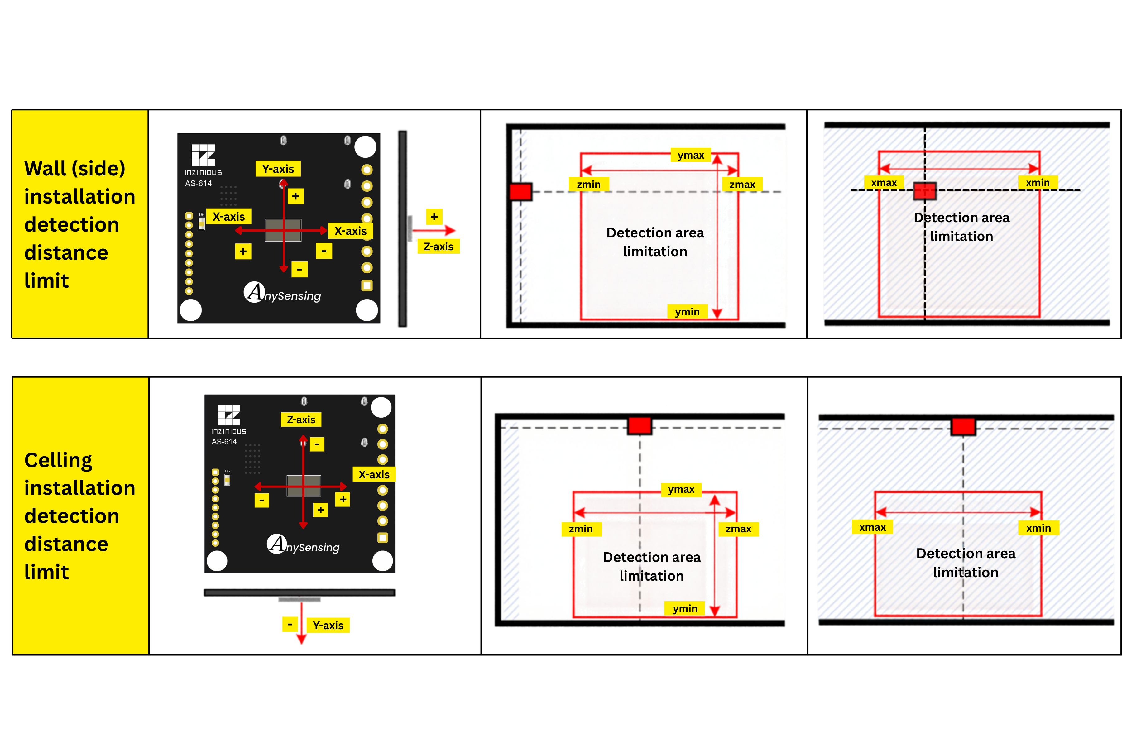
Set X, Y, and Z bounds in millimeters. Left and right in these views depend on the viewing direction; follow the labeled axes and verify signs after mounting.
Angle limits
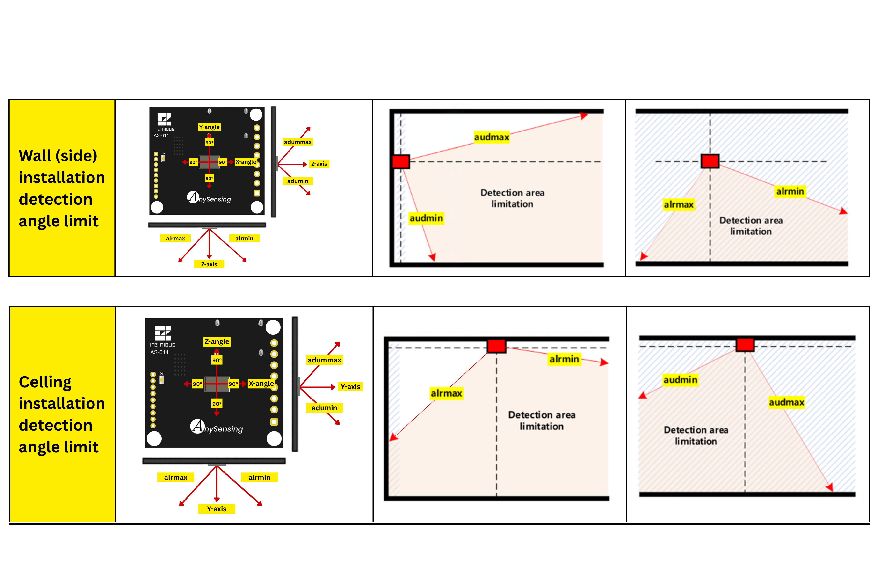
Use alrmin/alrmax and adumin/adumax for angle filtering. Command values use the documented 0–180° range; verify the resulting region with real targets.
Static-object detection
Distance-based Modes 1-4 normally prioritize moving objects. The static command enables limited fixed-object detection:
| Value | Documented fixed-object distance |
|---|---|
| 0 | Disabled |
| 1 | 1 m |
| 2 | 2 m |
| 3 | 3 m |
| 4 | 4 m |
| 5 | 5 m |
When motion exists, moving targets are output first. Fixed objects are detected only when no moving target is detected. The manual says fixed-object output has Z distance only and no direction information, but it does not define a separate fixed-object packet layout.
Use static detection sparingly The manual warns that enabling static-object detection can continuously report unwanted environmental objects. Test it in the final room and do not infer X/Y direction from a Z-only result.
Detection limitations
- Stationary people may disappear without enough micro-motion unless limited static detection is enabled.
- The manual gives examples rather than guarantees: breathing within about 2 m, conversation within 5 m, keyboard activity within 7 m, and larger motion beyond 7 m.
- Fans, air conditioners, air purifiers, curtains, cables, pets, and metallic clutter can create false or virtual targets.
- A measured person may fluctuate by 20-30 cm even when standing still.
- Targets directly behind another target may be hidden.
- Nearby people may merge into one target, with required separation increasing at longer distance.
Pass criteria
- Reported axis directions match the installed coordinate frame.
- One target crosses each ROI boundary at the measured location.
- Normal and extended packet lengths match the configured output.
- Zone digits change at verified physical boundaries.
- Two separated targets remain distinct at the intended working distance.
- Static-object mode, if used, does not create unacceptable persistent targets.
- Test records include hardware, firmware, enclosure, mounting, room geometry, target conditions, and acceptance thresholds.