
AS-614 UART, GPIO, Reset, and USB-C Integration
AS-614 uses an ASCII command-and-data protocol over UART. The USB-C connector is documented solely as a power input; use UART for host commands and sensor data.
UART format
| Item | Documented value |
|---|---|
| Encoding | ASCII |
| Data bits | 8 |
| Parity | None |
| Stop bits | 1 |
| Flow control | None |
| Commands | Lowercase |
| Command ending | LF or CR |
| Baud rate | 230400 bps |
| Normal command-response start/end | = / ! |
| Minimum command spacing | More than 500 ms |
The AS-614 manual does not document a baud-rate command or alternative supported rates.
Electrical level
The protocol specifies 3.3 V UART, then says 1.8 V, 3.3 V, and 5 V signal interfaces are possible. It does not define whether the pins are directly tolerant, translated, or dependent on a hardware configuration.
Use 3.3 V TTL UART by default Do not connect a 5 V UART directly unless the exact production hardware has documented level compatibility. The module power range of 3.3-7.0 V does not define UART pin tolerance.
Command transaction model
- Send one lowercase ASCII command terminated with LF or CR.
- Wait for the response ending in
!. - Leave more than 500 ms before the next command.
- After a mode or setting change, use the required reset workflow and wait for the module to restart.
- Discard initial buffered output after a mode change or restarting with
start. - Resume continuous parsing only after configuration is complete.
The manual shows query responses such as =15! but does not define standard strings for invalid range, unsupported command, unknown command, or internal error. Log every unrecognized response exactly as received. The ver example L25Aug16102.0! does not start with =; preserve it as firmware identification instead of discarding it as malformed.
Persistence and reset behavior
Changed settings are retained after power cycling.
| Command | Documented behavior |
|---|---|
reset | Software restart while retaining settings |
hreset | Restart equivalent to reconnecting power while retaining settings |
freset | Restore all settings to factory defaults |
start | Resume output; buffered state can appear first |
stop | Stop output while internal detection continues |
AS-614 does not document the per-mode mreset command used by some other products.
Host parser guidance
Mode-aware start markers include:
# * $ ~ < > % @ & ? { } ^ / \ =
Most documented frames end with !. Read UART as a byte stream:
- Buffer until a recognized marker.
- Select the grammar from the active mode, marker,
zone,exten, andwavesettings. - Continue to the expected end marker and exact length.
- Validate signs, decimal fields, and field widths.
- Timestamp raw bytes before conversion.
- Reject or quarantine malformed and undocumented frames.
Do not assign marker meanings globally. For example, < and > are occupancy packets in Modes 3/4, while the Mode 10 raw-data example also uses angle brackets.
Mode 10 requires a separate parser decision
The raw-data section shows <...>, the mode summary shows [...], and the general protocol says packets end with !. Confirm real licensed-firmware output before implementing Mode 10 framing.
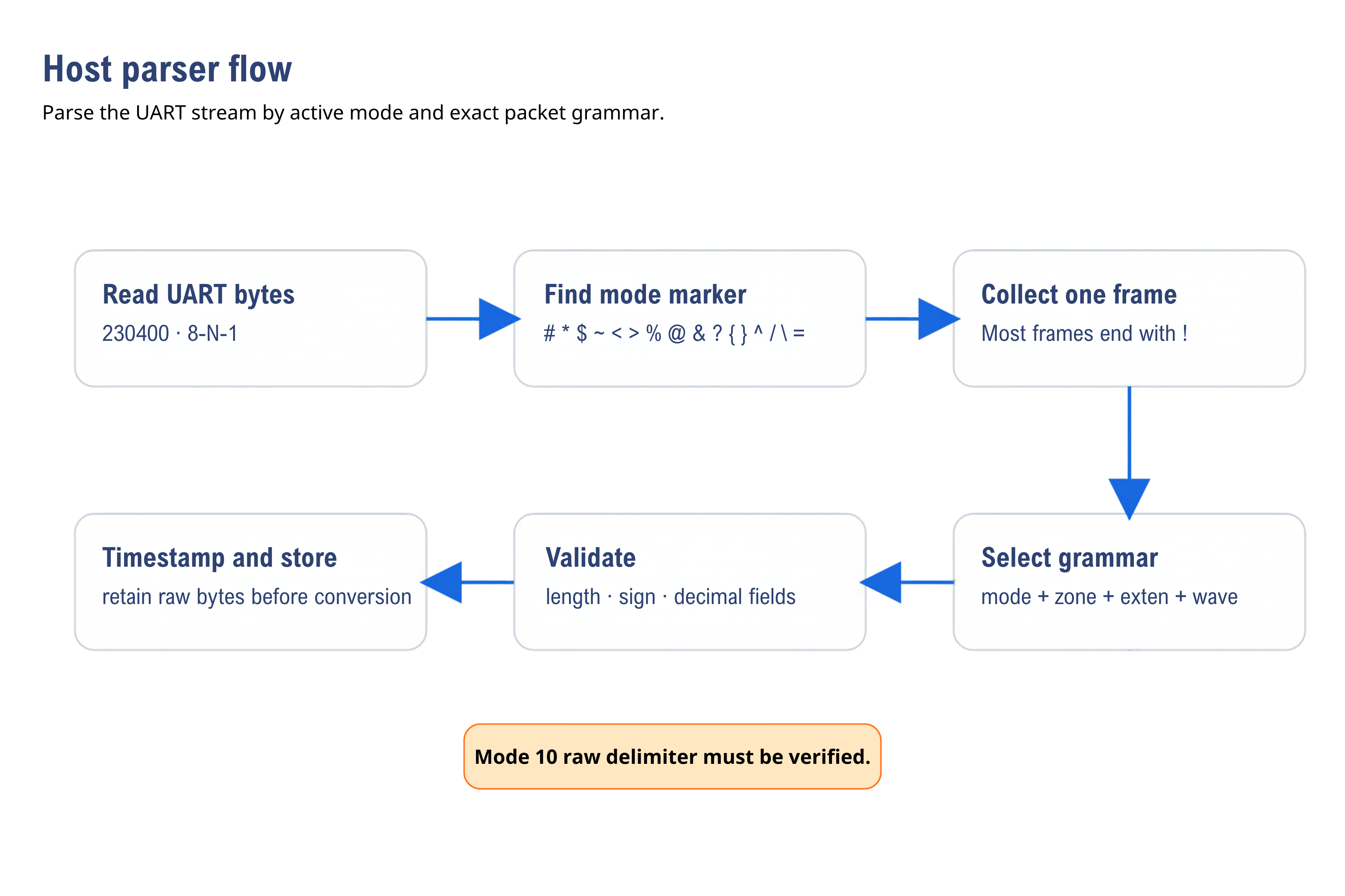
Select framing from the active mode and packet grammar; verify Mode 10 delimiters against actual firmware output.
GPIO behavior
GPIO defaults to output:
- High: target detected
- Low: no target detected
The manual says GPIO can be configured as input and then affects the last character of output data, but it does not provide the command, electrical behavior, or packet examples required to implement this feature.
NRST behavior
- Open or High: normal operation
- Low: reset
The source does not define minimum pulse width, pull resistor, voltage thresholds, or restart time. Keep NRST open during the initial UART test and validate any external reset circuit with production hardware.
USB-C behavior
The manual explicitly identifies J1 USB-C as being used solely for power supply. It does not document USB enumeration, a USB device class, serial data, firmware update, power delivery negotiation, or simultaneous-input behavior.
Use only one controlled power path during initial testing. Do not assume that USB-C exposes UART data.
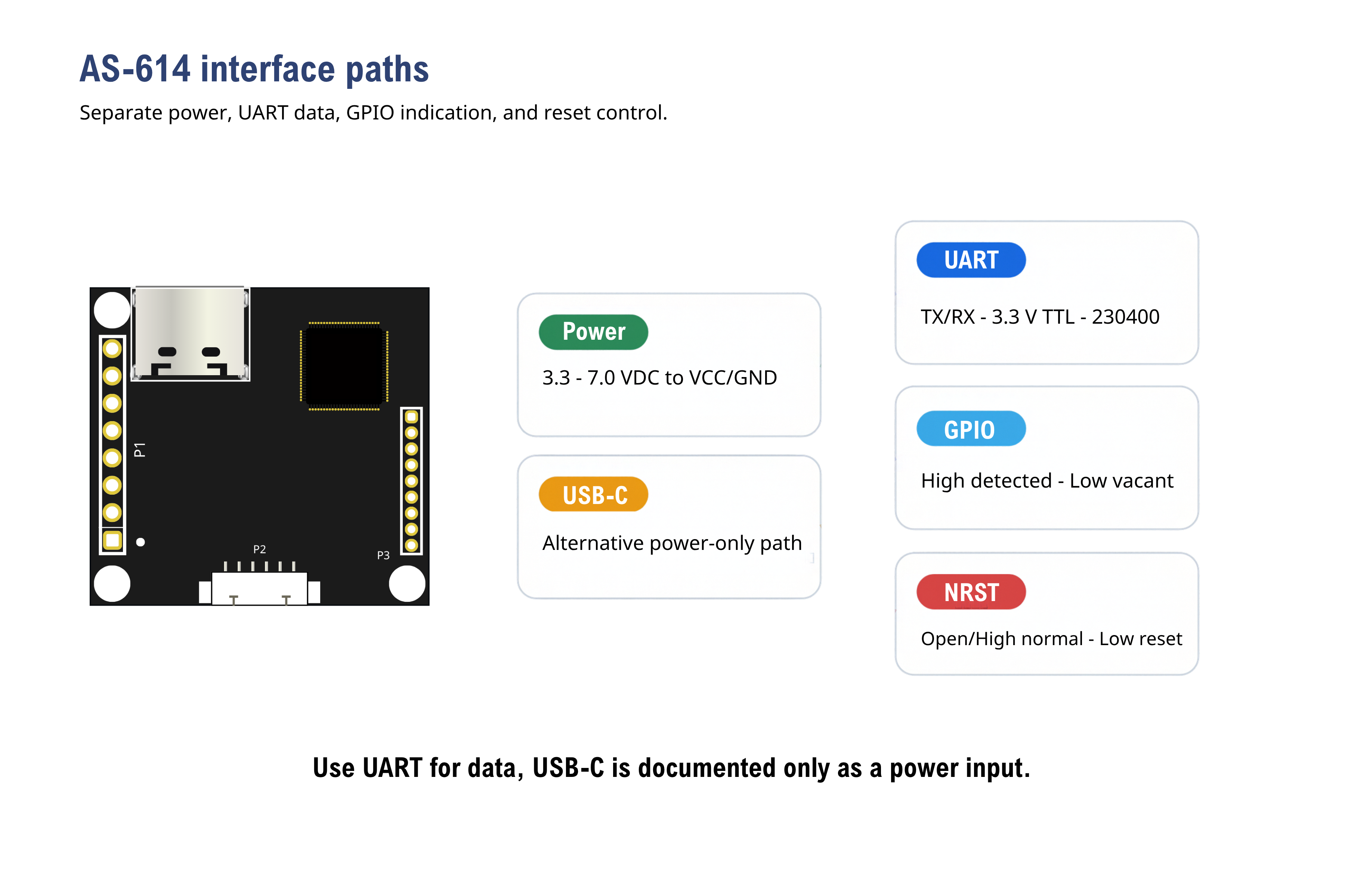
USB-C supplies power only. UART carries commands and data at 230400 bps with 3.3 V TTL logic.
Integration pass criteria
- UART is verified at 230400 bps, 8-N-1, no flow control, using 3.3 V TTL levels.
- The host enforces more than 500 ms between commands.
- Every command response is captured and unknown responses are retained.
- The parser handles partial, concatenated, malformed, vacancy, short-state, and normal frames.
- Configuration persistence is tested across
reset,hreset, and power cycles. - GPIO and NRST are measured electrically on production hardware.
- USB-C is used only for the documented power function.
- Mode 10 is disabled in the host until its delimiters and maximum frame size are confirmed.